Part 1: General requirements
SECTION 1 SCOPE AND GENERAL
1.1 SCOPE
This Standard sets out design and operational requirements for scaffolding systems,
scaffolding equipment and scaffolds. It also includes the specifications for catch platforms
erected on scaffolds. The stairway details also apply to temporary stairways for use on a
general construction site.
Where specified, particular requirements of other parts of this series of Standards will take
precedence over specific requirements of this Part.
WARNING: THE USE OF STANDARDS FROM ANOTHER COUNTRY WHEN
IMPORTING SCAFFOLDING EQUIPMENT AND/OR COMPONENTS MAY
NOT RESULT IN COMPLIANCE WITH AS/NZS 1576 SERIES. DESIGN,
PERFORMANCE AND/OR TEST CRITERIA MAY BE OF A LESSER LEVEL
IN OTHER STANDARDS. IT IS IMPERATIVE TO ENSURE THAT A
STANDARD FROM ANOTHER COUNTRY MEETS ALL THE
REQUIREMENTS OF AS/NZS 1576 SERIES BEFORE REFERENCING
SCAFFOLDING EQUIPMENT TO BE IN COMPLIANCE WITH THIS
STANDARD.
NOTES:
1 For the purposes of this Standard some types of equipment that incorporate temporary
working platforms may not be considered to be a scaffold. Examples of these types of
equipment may include the following:
(a) Equipment covered in other standards, for example—
(i) elevating work platforms, AS 1418.10(Int);
(ii) mast climbing work platforms, AS 1418.16;
(iii) portable ladders, AS/NZS 1892; and
(iv) formwork constructed primarily to support concrete, AS/NZS 3610.
(b) Stools under 1 m in height which may allow for height adjustment but do not require
assembly prior to use.
2 Trestle ladders are covered in the AS/NZS 1892 suite of Standards. Upon the review of
AS/NZS 1576.5, trestle ladder requirements will be removed from the AS/NZS 1892 suite of
Standards and incorporated into AS/NZS 1576.5.
1.2 NORMATIVE REFERENCES
The following are the normative documents referenced in this Standard:
NOTE: Document referenced for informative purposes are listed in the Bibliography.
AS
1170 Structural design actions
1170.4 Part 4: Earthquake actions in Australia
1391 Metallic materials—Tensile testing at ambient temperature
AS 1444 Wrought alloy steels—Standard and hardenability (H) series and hardened and
tempered to designated mechanical properties
1576 Scaffolding
1576.4 Part 4: Suspended scaffolding
1577 Scaffold planks
1594 Hot-rolled steel flat products
1720 Timber structures (all parts)
1734 Aluminium and aluminium alloys—Flat sheet, coiled sheet and plate
1831 Ductile cast iron
1832 Malleable cast iron
1833 Austenitic cast iron
1866 Aluminium and aluminium alloys—Extruded rod, bar, solid and hollow shapes
1874 Aluminium and aluminium alloys—Ingots and castings
1892 Portable ladders
1892.2 Part 2: Timber
2074 Cast steels
2321 Short-link chain for lifting purposes
2423 Coated steel wire fencing products for terrestrial, aquatic and general use
2759 Steel wire rope—Use, operation and maintenance
3569 Steel wire ropes
3678 Structural steel—Hot-rolled plates, floorplates and slabs
3679 Structural steel
3679.1 Part 1: Hot-rolled bars and sections
4100 Steel structures
4142 Fibre ropes
4142.2 Part 2: Three-strand hawser-laid and eight-strand plaited
4750 Electrogalvanized (zinc) coatings on ferrous hollow and open sections
AS/NZS
1163 Cold-formed structural steel hollow sections
1170 Structural design actions
1170.0 Part 0: General principles
1170.2 Part 2: Wind actions
1170.3 Part 3: Snow and ice actions
1554 Structural steel welding
1554.1 Part 1: Welding of steel structures
1576 Scaffolding
1576.2 Part 2: Couplers and accessories
1576.3 Part 3: Prefabricated and tube-and-coupler scaffolding
AS/NZS
1664 Aluminium structures
1664.1 Part 1: Limit state design
1664.2 Part 2: Allowable stress design
1665 Welding of aluminium structures
1892 Portable ladders
1892.1 Part 1: Metal
1892.3 Part 3: Reinforced plastic
1892.5 Part 5: Selection, safe use and care
2269 Plywood—Structural
4357 Structural laminated veneer lumber
4357.0 Part 0: Specifications
4600 Cold-formed steel structures
4680 Hot-dip galvanized (zinc) coatings on fabricated ferrous articles
4792 Hot-dip galvanized (zinc) coatings on ferrous hollow sections, applied by a
continuous or a specialized process
BS
2052 Specification for ropes made from manila, sisal, hemp, cotton and coir
ISO
1835 Short link chain for lifting purposes—Grade M (4), non-calibrated, for chain
slings etc.
1836 Short link chain for lifting purposes—Grade M (4), calibrated, for chain hoists
and other lifting appliances
3075 Short link chain for lifting purposes—Grade S (6) non calibrated, for chain slings
etc.
3076 Short link chain for lifting purposes—Grade T (8), non-calibrated, for chain
slings etc.
3077 Short-link chain for lifting purposes—Grade T, (types T, DAT and DT), finetolerance hoist chain
1.3 DEFINITIONS
For the purpose of this Standard, the definitions below apply.
1.3.1 Access platform
A platform that is used, or primarily intended to be used, to provide access for persons, or
for persons and materials, going to and from places of work, but does not include a working
platform.
1.3.2 Backing rails
Rails whose function is to transfer loads from infill panels to supporting posts.
1.3.3 Baseplate
A plate to distribute the load from a vertical loadbearing member to the supporting
structure.
1.3.4 Bay
1.3.4.1 Bay length
1.3.4.1.1 Minor, independent or mobile scaffold
The horizontal distance between the centres of any two longitudinally adjacent standards or
members, serving the purpose of standards, including spurs or cantilevered beams.
1.3.4.1.2 Suspended or hung scaffolding
The horizontal distance between the centres of any two longitudinally adjacent support
points, for example, anchorages for scaffolding hoists or connection points for hung
standards.
1.3.4.2 Bay width
1.3.4.2.1 Independent or mobile scaffolding
The horizontal distance between the centres of any two transversely adjacent standards or
members, serving the purpose of standards, including spurs or cantilevered beams, but does
not include bay extension formed by platform brackets.
1.3.4.2.2 Minor, suspended or hung scaffolding
The usable width of a working platform.
1.3.4.3 Bay extension platform
A portion of a working platform that protrudes beyond the face of a scaffold, adjacent to a
bay of an independent scaffold, forming an extension of that bay.
1.3.5 Brace
A member fixed to two or more members of a scaffold to increase the rigidity of the
scaffold.
NOTE: Braces are generally fixed diagonally.
1.3.6 Cantilever platform bay
A bay of scaffold that protrudes beyond the face of an independent scaffold or structure,
forming a discrete bay in addition to any bays in the independent scaffold.
1.3.7 Castor assembly
A wheel rotating on an axle fixed into a housing capable of being connected to the lower
end of a standard for the purpose of supporting and moving a scaffold.
NOTE: The housing may be fixed or may be capable of swivelling to allow the scaffold to be
moved horizontally in any direction.
1.3.8 Catch platform
A platform attached to a scaffold to contain debris falling from a working platform.
NOTE: A cantilevered portion of a catch platform is also called a fan.
1.3.9 Check coupler
A right angle, swivel or parallel coupler that is fixed hard against a loadbearing coupler, to
restrict or prevent slippage of that coupler along the tube.
1.3.10 Closed platform
A platform that is capable of being a working platform but is temporarily closed to any
loading or access by persons in accordance with the installation design.
1.3.11 Containment sheeting
Sheeting that encloses the outer facade of the scaffold to retain objects or particles within
the scaffold.
1.3.12 Cradle
That portion of a suspended scaffold that incorporates a suspended platform.
1.3.13 Edge protection
1.3.13.1 Guardrail
The highest rail in guardrailing fixed parallel to the platform.
1.3.13.2 Guardrailing
A system of rails or panels, or both, that provides edge protection at an edge of a platform.
1.3.13.3 Guardrailing panel
A panel that replaces a guardrail and midrail, and, may replace a toeboard.
NOTE: The panel transfers the design loads to the support, standards or posts and typically
incorporates mesh and a kick plate.
1.3.13.4 Handrail
A rail to provide a handhold on a platform, or stairway.
NOTE: It may form part of a guardrail.
1.3.13.5 Handrail panel
A panel that provides a handhold on a platform or stairway and replaces a handrail and
midrail. The centre of the panel comprises vertical balusters between the handrail and the
bottom rail.
1.3.13.6 Infill panel
A panel that requires backing rails to transfer design loads to supporting posts.
NOTE: It typically incorporates mesh as the infill and a kick plate. The panel spans between the
backing rails and the supporting posts and may replace a midrail, toeboard or both.
1.3.13.7 Kick plate
A plate (usually of metal), forming an integral part of a guardrailing panel or infill panel,
that prevents material from falling from the working platform.
1.3.13.8 Midrail
A rail or series of rails fitted approximately equidistant between a guardrail or handrail and
toeboard or platform.
1.3.13.9 Toeboard
A scaffold plank or a purpose-designed component fixed on edge at the edge of a platform,
to prevent material from falling from the platform.
1.3.14 Frame
A prefabricated assembly of defined width and height that consists of vertical members
separated by horizontal members.
NOTE: A frame may be constructed to enable a person to walk through.
1.3.15 Frame scaffold
A scaffold assembled from prefabricated frames, braces and accessories.
1.3.16 General construction site
A construction site where scaffolding and other temporary equipment is used to facilitate
work and the movement of persons between work locations.
1.3.17 Going
The horizontal distance between the nosing of one stair tread to the nosing of the next stair
tread above or below.
1.3.18 Integrated access
A non-removable ladder or step arrangement being part of a minor scaffold to enable
persons to access the working platform from the supporting structure.
1.3.19 Landing
A level area used to provide access to a stairway or ladder, or located at an intermediate
level in a system of stairways or ladders.
1.3.20 Ledger
A horizontal structural member of a scaffold, connecting adjacent standards, normally in
the direction of the larger dimension of a bay.
1.3.21 Lift
The vertical distance from the supporting surface to the lowest ledger or level at which a
platform can be constructed, or the vertical distance between adjacent ledgers or levels at
which platforms can be constructed.
1.3.22 Loading platform
A working platform on a scaffold that is primarily intended for the storage of materials and
equipment.
1.3.23 Low height working platform
Scaffolding, whose working platform is a maximum height of 1.5 m above the supporting
surface, rated as light duty, for the purposes of carrying out work using hand tools.
1.3.24 Minor scaffold
A scaffold that is of a light and portable nature and is restricted to having no working
platforms at a height that is greater than 2 m above the supporting surface.
1.3.25 Mobile minor scaffold
A minor scaffold able to support the live loads for which it was designed whilst being
supported on wheels that have the capability of being locked against rotation.
1.3.26 Modular scaffold
A scaffold assembled from prefabricated individual components, braces and accessories.
1.3.27 Modular minor scaffold
A minor scaffold that, prior to use, is constructed or assembled by following the
manufacturer’s instructions, using two or more previously unattached component parts.
1.3.28 Nosing
The leading edge of a stair tread.
1.3.29 Outrigger
Component (or components) that increases the effective base dimensions of a scaffold to
increase its stability
1.3.30 Platform
A surface on a scaffold to support persons, materials or both.
1.3.31 Platform bracket
A type of bracket attached to the scaffold to support a bay extension platform adjacent to a
bay of an independent scaffold.
NOTE: A platform bracket is also known as a hop-up or console bracket.
1.3.32 Platform support
An integrated assembly not comprising standards that support a platform.
1.3.33 Prefabricated platform
A framed assembly of one bay length incorporating a working surface that is capable of
connecting to its support structure in such a way as not to be inadvertently dislodged. One
or more platforms may be required to suit the bay width.
1.3.34 Prefabricated scaffold
An integrated system of prefabricated components manufactured in such a way that the
geometry of assembled scaffolds is pre-determined.
1.3.35 Protective device
A device that will arrest the descent and support a cradle or boatswain’s chair in the event
of failure of the suspension rope or the scaffolding hoist.
NOTE: A protective device may also prevent an overspeed descent.
1.3.36 Putlog
A horizontal structural member spanning between adjacent ledgers, or between a ledger or
standard and an adjacent wall, and which can be used to support a platform.
1.3.37 Raker
An inclined tube fixed between a scaffold and the supporting structure to keep the scaffold
stable.
1.3.38 Rigid minor scaffold
A minor scaffold that, apart from the folding or sliding of captive components into place, is
not required to be assembled prior to use. This scaffold is either rigid, where the complete
in-service shape is fixed, or parts of the scaffold fold out or slide out to form the complete
in-service shape.
1.3.39 Rise
The vertical distance between the top of one stair tread and the next stair tread above or
below.
1.3.40 Scaffold (also referred to as scaffolding)
A temporary structure, including access platforms, working platforms, catch platforms and
landing platforms.
1.3.41 Scaffolding equipment
Any component, assembly or machine used or intended to be used as part of a scaffold.
1.3.42 Scaffolding system
Designed combination of components that can form a scaffold.
1.3.43 Scaffold plank
A decking component, other than a prefabricated platform, that is used or intended to be
used to form a platform.
1.3.44 Secondary rope
A rope not normally carrying the weight of a cradle and the imposed load, but which is
rigged for use with a protective device.
1.3.45 Soleplate
An item, other than a baseplate, used to distribute the point load of a loadbearing member to
the ground or other supporting structure.
1.3.46 Spur
An inclined loadbearing member that transmits a load to another structural member of the
scaffold or to the supporting structure.
1.3.47 Standard
A vertical structural member of a scaffold that transmits a load to the supporting structure.
1.3.48 Stairway flight
A single continuous set of rises and goings.
1.3.49 Supporting structure
Any structure, structural member, foundation or surface that supports a scaffold.
1.3.50 Suspension rig
That portion of the structure in a suspended scaffold (including the trolley track), mounted
at a level higher than the cradle to support and position the cradle.
1.3.51 Tie
A member or assembly of members used to stabilize a scaffold from a supporting structure.
1.3.52 Toeboard
A scaffold plank or purpose-designed component fixed on edge at the edge of a platform, to
prevent material from falling from the platform.
1.3.53 Transom
A horizontal structural member of a scaffold that is used to connect adjacent standards,
normally in the direction of the smaller dimension of a bay.
1.3.54 Tread
The horizontal surface of a stairway component that supports a person’s foot.
1.3.55 Working face
A face of a building or structure at which a scaffold has been erected to enable work to be
carried out at some stage during the project.
1.3.56 Working load limit
The maximum unfactored load, including permanent and imposed actions, that the
components or system has been designed to support.
1.3.57 Working platform
A platform on a scaffold positioned at a work location for supporting personnel, equipment
and materials and used to provide a working area.
1.4 TYPES OF SCAFFOLD
Common types of scaffold include the following:
(a) Independent scaffolds Scaffolds that consist of two or more longitudinal rows of
standards connected longitudinally and transversely. Independent scaffolds, typically
but not necessarily, are constructed from prefabricated components, prefabricated
frames, tubes and couplers, or timber components with bolted connections. Forms of
independent scaffolds include the following:
(i) Tower scaffold An independent scaffold that consists of four standards,
connected longitudinally and transversely, or two frames in plan connected
transversely, to create a scaffold of one bay.
(ii) Mobile scaffold A freestanding independent scaffold that is mounted on
castors.
(iii) Hung scaffold An independent scaffold that hangs statically from another
structure. The scaffold may be hung by means of scaffold tubes, prefabricated
components, timbers, ropes or chains, and may incorporate traversing features
enabling it to be moved laterally when in use, but is not capable of being raised
or lowered when in use.
(iv) Birdcage scaffold An independent scaffold that consists of three or more
longitudinal rows of standards and, therefore, two or more bays in width.
(b) Single pole scaffolds Scaffolds that consist of a single row of standards connected
longitudinally. The standards may be supported from below or from above or a
combination of both. Single pole scaffolds incorporate putlogs or transoms, either
built into the adjacent supporting structure, or cantilevered from the supporting
components, or a combination of both. Single pole scaffolds typically, but not
necessarily, are constructed from prefabricated components, scaffold tubes and
couplers, or timber components with bolted connections.
(c) Void scaffolds Scaffolds that consist of a working platform supported on horizontal
members that are in turn supported directly by the surrounding permanent structure
and typically are used to fill a void or in a shaft.
(d) Suspended scaffolds Scaffolds that incorporate a platform suspended by one (or
more) flexible steel wire rope, and which is capable of being raised or lowered when
in use by means of powered or manually operated scaffolding hoists. Suspended
scaffolds may incorporate single cradles, articulated cradles or multi-deck cradles.
Suspended scaffolds do not include industrial rope access equipment. Forms of
suspended scaffold include the following:
(i) Swing stage scaffold—incorporates one or more cradles supported by a single
longitudinal row of suspension ropes.
(ii) Double rope scaffold—suspended scaffold that consists of one or more cradles
supported by two longitudinal rows of suspension ropes.
(iii) Work cage scaffold—consists of a cradle supported by a single suspension rope.
(iv) Boatswain’s chair—consists of a chair or similar platform designed for a person
to sit in, and supported by a single suspension rope.
(e) Bracket scaffolds Scaffolds that consist of nominally triangular brackets fixed to the
supporting structure to support a platform. Forms of bracket scaffolds include the
following:
(i) Tank bracket scaffold—fixed to the sides of tanks, silos, structural steel
members or similar structures.
(ii) Stud bracket scaffold—fixed to the wall studs of house wall frames or
structures of similar construction.
(iii) Top plate hung bracket scaffold—supported from the top plate of house wall
frames or structures of similar construction.
(iv) Ladder bracket scaffold—formed by brackets supported from the rungs of
single or extension ladder resting against the supporting structure.
(f) Trestle scaffolds and trestle ladders Scaffolds that consist of prefabricated trestles
supporting a platform. Forms of trestle scaffolds include the following:
(i) Frame trestle scaffold—consisting of freestanding frame.
(ii) Putlog trestle scaffold—consisting of trestles incorporating putlogs that are
supported on the inside of the scaffold by the supporting structure.
(iii) Trestle ladder scaffold—consisting of freestanding trestle ladders, which may
or may not incorporate stabilizing arms.
(iv) Splithead trestle scaffold—consisting of self-supporting stands that support
horizontal beams, such as scaffold planks resting on their edge, as putlogs.
(g) Spur scaffolds Scaffolds or portions of scaffolds, supported by inclined loadbearing
members connected directly or indirectly to supporting standards.
(h) Cantilever scaffolds Scaffolds or portions of scaffolds supported by nominally
horizontal loadbearing cantilevered members, which may be purpose designed
brackets.
(i) Minor scaffolds Forms of minor scaffolds include the following:
(i) Mobile scaffold A scaffold that is able to support the live loads for which it
was designed whilst being supported on wheels that have the capability of being
locked against rotation.
(ii) Modular scaffold A scaffold that, prior to its use and by following the
manufacturer’s instructions, is constructed or assembled from two or more
previously unattached components parts.
(iii) Rigid scaffold A rigid scaffold where the complete in-service shape is fixed or
parts of the scaffold fold out or slide out to form the complete in-service shape.
A rigid minor scaffold, apart from the folding or sliding of captive components
into place, is not required to be assembled prior to use.
(iv) Work platform A rigid scaffold where the platform area is not greater than
0.5 m2
, has a maximum length not greater than 1 m and has a working load limit
of 150 kg.
1.5 MARKING OF SCAFFOLDING EQUIPMENT
1.5.1 Scaffolding equipment
All scaffold components, except for baseplates, soleplates, timber of known grade and plain
tube that is not part of a prefabricated component, shall be marked with a symbol or letters
to identify the scaffold manufacturer or supplier and, as appropriate, the system type.
The marking shall be readily visible and of a size that will be clearly legible for the
expected life of the component.
The size of the lettering may take account of the size of the component.
Equipment manufactured prior to publication of this Standard is not required to carry the
specified marking.
1.5.2 Minor scaffolds
All minor scaffolds shall comply with the marking requirements of Clause 1.5.1, except that
the marking shall identify the Australian or New Zealand manufacturer or supplier. The
marking may take the form of a label, provided the label complies with Clause 1.6.3.
1.6 PRODUCT INFORMATION
1.6.1 Documented information
Appropriate documented information, in plain English and SI units, shall be provided on the
scaffolding system or scaffolding equipment. The information shall identify the supplier
and the means of product identification. Except where specified otherwise by this Standard,
the information shall include at least the following:
(a) A list of all components with descriptions from which each can be identified.
(b) Instructions for erection, dismantling, movement of mobile scaffolds, use,
transportation and storage.
(c) Guidance for the servicing and inspection of the equipment and the rejection of
damaged components.
(d) The nominal weight of each component, in kilograms.
(e) Details giving sufficient information to determine—
(i) duty loadings;
(ii) maximum heights; and
(iii) maximum number of working platforms.
(f) Relevant limitations.
1.6.2 Labelled information
For freestanding, single bay tower scaffolds, where the top working platform is no more
than 6 m above the supporting surface, and minor scaffolds, the requirements of
Clause 1.6.1 may be considered to be met, provided the following information is displayed
in a prominent position on the scaffold, or an essential component of the scaffold:
(a) Instructions for erection, dismantling, use, transportation and storage, including—
(i) advice on safe means of access (e.g. warning against descending in a forward
direction) from minor scaffolds provided with rung or step access; and
(ii) where the scaffold is not of an insulated type the words ‘DO NOT USE WHERE
ELECTRICAL HAZARD EXISTS’ in the largest lettering practicable.
(b) The working load limit, in kilograms and, where applicable—
(i) maximum height of working platform;
(ii) maximum number of working platforms; and
(iii) any other relevant limitations.
1.6.3 Labels
Where documented information complying with Clause 1.6.1 is not supplied with the
scaffold, the information required by Clause 1.6.2 shall be in the form of labels that—
(a) comply with the test requirements for specified labels in AS/NZS 1892.1;
(b) are appropriately located and/or protected to guard against wear, abrasion and
disfiguring; and
(c) are attached by a method that does not adversely affect the strength of the label, or
the component to which it is attached.
1.7 ALTERNATIVE DESIGN METHODS AND MATERIALS
Alternative design methods and, materials, which are not mentioned in this Standard, may
be used, provided it can be demonstrated that the resulting scaffolding equipment satisfies
the requirements specified in this Standard.
Service life durability shall be a consideration in any assessment of new materials.
Part 2:Design Requirements
2.1 SCOPE OF SECTION
This Section specifies the parameters that need to be applied to produce a safe scaffold that
is fit for its intended purpose. There are effectively two types of design required as follows:
(a) System design The design of the scaffolding system including its constituent
components, which may be combined to form a scaffold.
(b) Installation design The design of a scaffold for a particular installation, based on all
the anticipated loads and its intended usage. This will result in either the use of an
appropriate scaffolding system or a scaffold purpose-designed for the installation.
2.2 DESIGN METHODS
2.2.1 General
The design of the scaffolding systems, scaffolding equipment and scaffolds shall take into
account the following:
(a) The strength, stability and stiffness of the supporting structure.
(b) The provision of edge protection on platforms.
(c) The handling and repeated use of components normally associated with scaffolding.
(d) The safety of persons engaged in the erection, alteration and dismantling of the
scaffold.
(e) The safety of persons accessing and moving along and around the scaffold.
(f) The safety of persons using the scaffold.
(g) The safety of persons in the vicinity of the scaffold.
(h) The environment in which the scaffold is used.
C2.2.1(h) Environmental conditions may have adverse effects on scaffolding
systems. Conditions such as corrosive atmospheres and marine environments may
corrode components. Weather conditions, such as wind or extreme temperatures,
will impose additional loads.
(i) The duration the scaffold is expected to remain in use.
Scaffolding systems and equipment shall be analysed and designed in accordance with
Clause 2.2.2 or tested in accordance with Clause 2.2.3.
Where a scaffold is outside the configuration specified by the supplier’s information but
using components that have been previously tested, such configuration shall be confirmed
by theoretical analysis or testing in accordance with Clauses 2.2.2 and 2.2.3.
2.2.2 Theoretical analysis
The scaffold structure and its component members and connections shall be analysed and
designed by limit state or permissible stress procedures in accordance with the relevant
Australian or New Zealand material Standards, and as modified by the requirements of this
Standard.
When using the permissible stress method it shall provide at least an equivalent design
performance level achieved by the limit state method.
NOTES:
1 For the design of new components or a group of components, see flowchart in Appendix C.
2 For structural design of a scaffold see flowchart in Appendix D.
2.2.3 Testing
The structural capacities of scaffolding equipment and systems shall be determined by test
in accordance with the relevant parts of this Standard.
2.3 MATERIAL AND TUBE COMBINATIONS
For a scaffold incorporating plain tube, the analysis and design shall consider the most
adverse combination of tubes by wall thickness, strength of the tube material, or both.
The materials and design considerations for general scaffolds shall be in accordance with
Appendix A.
The materials, design considerations and manufacture of minor scaffolds shall be in
accordance with Appendix B.
C2.3 The wall thickness of 48.3 mm outside diameter plain steel tube that is used in
tube-and-coupler scaffolds can range from the considerable quantities of old stock tube
having a wall thickness of 4.88 mm to recent stock of tubes having a wall thickness of
3.2 mm and 4 mm. All these tubes have differing mass per linear metre. It is not possible
from an external inspection to readily determine the wall thickness of all tubes in an
erected scaffold and hence to determine whether a scaffold has been erected with tubes
of the wall thickness used in the design. Accordingly, this Clause requires the designer
to assume the worst case for all tubes delivered to the site, that is the self-weight is
calculated on the basis that all tubes have a wall thickness of 4.88 mm; all loadbearing
tubes are assumed to have a wall thickness of 4 mm in Australia and 3.2 mm galvanized
tube in New Zealand, unless it can be clearly demonstrated that 3.2 mm wall thickness
tube will not be supplied, in which case the strength of loadbearing members should be
calculated on the basis that all tubes have a wall thickness of 4 mm.
2.4 SYSTEM COMBINATIONS
Components from different prefabricated scaffolding systems shall not be mixed unless the
load capacity of the mixed scaffolding system has been assessed by theoretical analysis or
testing in accordance with this Standard, and—
(a) the components are of compatible size and strength and have compatible deflection
characteristics;
(b) the fixing devices are compatible; and
(c) the mixing does not lessen the strength, stability, stiffness or suitability of the
scaffold.
The following system combinations shall not be used unless designed in accordance with
this Standard:
(i) Steel prefabricated scaffolding systems used in conjunction with aluminium
prefabricated scaffolding systems.
(ii) Aluminium scaffold tubes used as principal structural members in a steel
prefabricated scaffold.
(iii) Steel scaffold tubes used as principal structural members in an aluminium
prefabricated scaffold. This does not apply to the use of tie tubes or members such as
guardrails.
2.5 ACTIONS
2.5.1 General
The actions to be considered shall include permanent actions, imposed actions and
environmental actions.
2.5.2 Permanent actions
The permanent actions shall include the self-weight of the scaffold structure and
components, including working platforms, closed platforms, catch platforms, access
platforms stairways, ladders, screens, containment sheeting, platform brackets, suspension
ropes, secondary ropes, traversing ropes, tie assemblies, scaffolding hoists, electrical cables
and any other attachment, where appropriate.
2.5.3 Imposed actions
2.5.3.1 Duty actions
2.5.3.1.1 General
The duty action is the imposed action applied to a working platform within a bay. It shall
include the following:
(a) The weight of persons.
(b) The weight of materials and debris.
(c) The weight of tools and equipment.
(d) Impact forces.
The weight of a person shall be taken as not less than 100 kg (1000 N).
2.5.3.1.2 Categories
Duty action shall be one of the following categories:
(a) Light duty A total load of 2.2 kN per bay, which includes a single concentrated load
of 1.2 kN.
(b) Medium duty A total load of 4.4 kN per bay, which includes a single concentrated
load of 1.5 kN.
(c) Heavy duty A total load of 6.6 kN per bay, which includes a single concentrated load
of 2 kN.
(d) Special duty The largest intended load but not less than 1 kPa.
(e) Loading platforms The working load limit of a loading platform for material or
equipment storage shall be the largest intended load but not less than 5 kPa. The
imposed action shall include a factor of 1.25 to allow for the effect of impact.
(f) Bay extension platform The load acting on a bay extension platform shall be limited
to light duty loading. The total load on the working platform and the adjacent bay
extension platform shall not exceed the duty loading of the working platform, unless
the combined platforms are specifically designed for special duty category.
The single concentrated load shall be placed in the most adverse position within the bay and
be assumed to act over an area of not more than 100 mm × 100 mm.
WARNING: IT IS IMPERATIVE THAT THE NUMBER OF PLATFORMS
THAT WILL BE INSTALLED WITH DECKING, WORKED ON AT ANY ONE
TIME AND THEIR DUTY CATEGORIES BE ESTABLISHED PRIOR TO
DESIGNING THE SCAFFOLD FOR A PARTICULAR INSTALLATION.
DESIGNING A SCAFFOLD TO SUPPORT A LESSER NUMBER OF WORKING
PLATFORMS OF A LOWER DUTY CATEGORY THAN WILL BE APPLIED
MAY HAVE CATASTROPHIC CONSEQUENCES.
2.5.3.1.3 Concentrated loads
The location of the single concentrated duty load that produces the most adverse effect may
vary depending on the component or load path under consideration. Concentrated load
locations that should be considered include—
(a) at midspan of platforms or planks;
(b) at midspan of transoms;
(c) immediately adjacent to standards or spurs; and
(d) at outermost point of cantilevered members.
The single concentrated duty load need not be considered to act within—
(i) 250 mm of a bay boundary at which edge protection is fitted; and
(ii) 50 mm of a bay boundary at which edge protection is not fitted.
Where a bay boundary is taken to mean a line between adjacent standards (or spurs) or the
outermost ends of platform brackets or cantilever platform supports (for installation design
the external bay boundary may be taken as the edge of the installed platform)—
(A) a pair of concentrated loads in adjacent bays (or bay extensions) may be considered to
act at least 500 mm apart; and
(B) the concentrated load relevant to a bay extension is that specified for light duty and
may be considered not to act simultaneously with the concentrated load in the
adjacent bay.
NOTE: The location loads for special duty and loading platforms are uniformly distributed loads
and hence are given as Kilopascals (kPa) [(kilonewton per square metre, kN/m2
)].
C2.5.3.1.3 Categories of actions are intended to reflect the type of work that will be carried out on a working platform. This work reflects the number of persons that will be on the platform at the same time together with materials, tools and equipment required for that work. The type of work relates to the minimum specified width of a working platform to ensure that where materials to be used by workers are stacked on the platform there is sufficient space for materials as well as enabling the workers to move safely and freely along the platform whilst working. Working platforms are rated by their duty category. It is common to rate a scaffold the same as the highest duty rating of a working platform. Whilst a scaffold system may have been designed or tested to support a limited number of working platforms of a specific duty category, it does not automatically apply that a particular scaffold installation can support every working platform at that duty category and, accordingly, the whole scaffold cannot be rated at that duty category. The load on the scaffold is a combination of the duty action, sometimes called the live load, and the self-weight or permanent actions of the components of the scaffold, sometimes called the dead load. It should be remembered that the weight of planks on platforms when combined with toeboards, guardrails and midrails are a significant part of the self-weight of a scaffold. The greater the number of lifts in a scaffold, which are fully planked and fitted with edge protection, the greater the self-weight of the scaffold. The self-weight scaffold is further increased if containment sheeting is attached to the outside of the scaffold. When the bays that are planked become working platforms loaded to a duty category (live load), the total load on the scaffold increases significantly. It must be clearly understood that the commonly used terminology of a ‘heavy duty scaffold’ does not mean that the scaffold at maximum design height has sufficient strength to support platforms and edge protection installed at every level or that all working platforms can be rated as heavy duty. The extra dead load of platforms installed at every level, when combined with the duty actions resulting from a number of working platforms loaded at the same time, will significantly increase the total load on the scaffold and, unless controlled, may exceed the design capacity of the scaffold as determined by analysis or by testing. The effective loadbearing capacity of the standards in the scaffold can be increased by reducing the effective length of the standards between ledgers and transoms. Such capacity increase requires determination by structural analysis or by testing. In effect, describing a scaffold as ‘heavy duty’ really means that the scaffold has bays of sufficient dimensions such that they can be fitted with working platforms that can be designated as ‘heavy duty’ as specified in Clause 3.6. In a similar manner, scaffolds may be described as medium duty or light duty without the full height of the scaffold being able to support all working platforms of the designated duty category. For scaffolding, there are two forms of design. The system design refers to the prefabricated system that is designed for a range of applications where, at a later stage, the system design information is used by the installation design for a specific installation scaffold. The installation design may also be for a tube-and-coupler scaffold for a specific installation. The installation designer must ensure that the total loading of the working platform, comprising of live loads, heavy, medium, light or special duty, in a single bay of a scaffold, when combined with the self-weight of all platforms in that bay, does not exceed the scaffold capacity as determined by analysis or testing.
Where it is likely during the life of a scaffold installation that the duty ratings of working platforms may vary, the installation design will need to include sufficient information on the acceptable combinations of duty ratings that would comply with the design capacity of the scaffold as established by the system designer (see Clause 2.6). The addition of containment sheeting, platform brackets and environmental actions will affect the total loads on the scaffold and may significantly reduce the number of platforms that can be installed, including working platforms and their duty ratings, unless the scaffold system has been designed for these loads. It may be that the installation design has allowed for all or most levels of the scaffold to be fitted with planks but does not allow for all such platforms to be designated as working platforms at the one time. Where platforms are fully decked but no materials or persons are permitted to be on such platforms by the installation design, such platforms should be classified as ‘closed platforms’ to differentiate them from ‘working platforms’. The installation design may allow different levels of platforms to be designated as ‘working platforms’ or ‘closed platforms’ during various stages of the building construction. Light duty category relates to a working platform that is intended to support a person or persons where the combined weight of the person(s) and the accompanying tools, equipment and materials does not exceed 225 kg. Medium duty category relates to a working platform that is intended to support persons and limited materials on the platform and where the combined weight of the persons, materials, equipment and tools may exceed 225 kg but does not exceed 450 kg. Heavy duty category relates to a working platform that is intended to support persons and materials on the platform where the combined weight of the persons, materials, equipment and tools may exceed 450 kg but does not exceed 675 kg. Special duty category relates to a working platform where the specified categories of light, medium and heavy are not appropriate. Examples of such cases are where the bay dimensions are not apparent on the surface of the working platform, as occurs with a birdcage scaffold, or where materials and equipment may be distributed over a working platform in bays larger than those of typical independent scaffolds. 2.5.3.1.4 Access platform Except for ladder landings and stair landings, the duty imposed actions applied to an access platform shall be not less than heavy duty. C2.5.3.1.4 Access platforms by definition give access to and from places of work to persons, materials and equipment. It is likely that the installation designer will have less influence over the site loading of an access platform than a working platform due to the dynamics of activity during peak periods of work, at work commencement and at finish times. The likelihood that several workers or a combination of workers and materials utilizing the access platform at the one time warrant that access platforms be rated as heavy-duty or greater. For example, a typical access platform can be constructed from bays 2.4 m by 1.2 m, each of which has an area of 2.88 m2 . The minimum duty rating specified by Clause 2.5.3.1.4 is heavy duty, which represents a distributed load of approximately 2.3 kPa per bay of these dimensions. Access platforms constructed in bays of greater area, or where bay size is indeterminable, should be designed to withstand an imposed action of not less than 2.5 kPa.
2.5.3.1.5 Ladder landing bay
The duty actions applied to those components specifically supporting a ladder landing shall
be those imposed from the intended number of persons using the landing at any one time.
2.5.3.2 Component-imposed actions
This Clause does not apply to the installation design.
The design of scaffolding equipment shall comply with the following requirements:
(a) Standard spur or similar member Where a standard, spur or similar member is
intended to support working platforms in any bay, it shall be designed for the
combination of permanent and imposed actions including the maximum intended duty
action per working level on any working platform to be supported by these members.
The proportion of the imposed action on any standard, spur or similar member shall
be one quarter of the duty imposed action on each the working platforms in the bay
supported by the standard.
That part of a standard that supports other components shall be designed for the
imposed actions, e.g. transoms, platform brackets.
(b) Where a standard, spur or similar member is intended to support bay extension
platforms, it shall be designed for an imposed action, per working level, determined
by rational analysis resulting from—
(i) one-quarter of the platform action in each bay, applied at the outer standard;
(ii) one-quarter of the platform action in each bay, minus 2 kN, applied at the inner
standard; and
(iii) 2 kN applied at the outermost point of the bracket supporting the bay extension
platform.
(c) Guardrails or handrails The imposed action acting on a guardrail and handrails
shall be the greater of a 550 N concentrated load acting outwards or downwards at
any point on the guardrail, or a line load of 330 N per linear metre acting outwards or
downwards on the top rail or edge. An upward load of 300 N shall be applied
separately to the component at the connection to the supporting member.
NOTE: The 300 N upward load is to check the adequacy of the connection.
(d) Midrails The imposed action acting on a midrail shall be the greater of a
concentrated load of 300 N acting outwards or downwards at any point on the rail,
edge or post, or linear load of 175 N per lineal metre acting outwards or downwards
on the rail. An upward load of 300 N shall be applied to the component at the
connection to the supporting member.
NOTE: The 300 N upward load is to check the adequacy of the connection.
(e) Toeboards and kick plates The imposed action acting on a toeboard and kick plate
shall be a concentrated load of 150 N acting outwards at any point on the toeboard or
kick plate.
(f) Guardrail posts The post and the connection of the rails to the post shall be
designed to resist the loads imposed by the guardrail and midrail. Loads transferred to
the post from the guardrail and midrail are not required to act simultaneously.
NOTE: Typically, guardrail posts is formed from scaffold standards from the scaffold system.
(g) Ledgers, putlogs and transoms A ledger, putlog or transom that is intended to
support platforms in adjoining bays shall be designed for the largest intended imposed
action, which shall be not less than two-thirds of the total imposed actions resulting
from the designed total duty loads on each of the adjoining bays.
C2.5.3.2(g) The two thirds of the bay load specified for the design of a ledger, putlog or transom is to be used only in the design of the component and is not intended to be used when calculating the total imposed action on the scaffold. For a prefabricated scaffold system where a range of duty loads is possible for the same equipment, the greatest likely duty load will control the maximum permitted deflection. Where a transom is of a length that limits the width of a working platform as specified in Clause 3.6.2, the lesser duty action, medium or light will apply when determining the maximum permitted deflection permitted by Clause 2.7.4(h).
(h) Scaffold tie The scaffold tie and its connection to the scaffold component shall be
designed to resist a tension or compression force of not less than 6.0 kN, unless
specifically designed and documented for lower forces.
(i) Panels:
(i) Guardrailing panels Guardrailing panels shall be designed in accordance with
the above load requirements for guardrails, midrails and, where applicable,
toeboards. Loads shall be applied at the midspan of the component that it
replaces. The midrail concentrated load shall be applied horizontally outwards
at the centre of the panel over an area of a maximum of 300 mm × 300 mm.
(ii) Infill panels Infill panels shall be designed in accordance with the above load
requirements for the component(s) it replaces. The concentrated load shall be
applied horizontally outwards to the infill area at the midspan of the
component(s) that it replaces. The load may be distributed over an area of a
maximum of 300 mm × 300 mm. The midrail upward loading does not apply.
(iii) Handrail panel Handrail panels shall be designed in accordance with the load
requirements for handrails, midrails and toeboards specified in Items (c), (d)
and (e) of Clause 2.5.3.2. All loads shall be applied horizontally outwards. The
midrail concentrated load shall be applied at the centre of the panel spanning at
least two vertical balusters over an area of a maximum of 300 mm × 300 mm.
The toeboard concentrated load shall be applied at the midspan of the bottom
rail.
(j) Cantilever platform support A cantilever platform support shall be designed for the
largest intended imposed action, which shall be not less than two-thirds of the total
imposed actions resulting from the designated total duty loads on each of the
adjoining bays. For a single bay, two-thirds of the platform loadings shall be applied
at each support. The imposed action shall include a single concentrated load (acting
downwards) equal to the largest intended concentrated load, but not less than that
specified in Clause 2.5.3.1.2 (as applicable), acting in the most adverse position on
the platform.
(k) Platform bracket A platform bracket shall be designed for the following load cases,
which shall be considered separately and the loads applicable to the bracket shall not
be additive:
(i) Load applied along the length of the bracket, which shall be not less than twothirds of the total load resulting from the designated light duty loads on each of
the adjoining platforms.
(ii) A single concentrated load of 2 kN acting downwards at the end of the bracket.
NOTE: The 2 kN action should be applied at a nominal distance of 50 mm inside the
outermost end of the bracket.
A platform bracket shall be designed so that it cannot be accidentally dislodged or
rotated when in use. A stop shall be securely fixed to the outer end of the horizontal
member to prevent dislodgment of planks.
C2.5.3.2(k) A platform bracket supports a bay extension platform on an
independent scaffold or a platform off a permanent or temporary construction.
These platforms are limited to light duty category.
A cantilever platform support refers to a cantilever platform supported off an
independent scaffold that may be loaded to any duty category.
(l) Catch platform support A catch platform support shall be designed for the largest
expected load, which shall be not less than 1 kPa uniformly applied.
C2.5.3.2(l) An expected load of 1 kPa on a catch platform is reasonable in
circumstances where the catch platform is vertically adjacent to the working
platform. Consideration needs to be given to the vertical distance between the
working platform and the catch platform, the duty and nature of the work being
undertaken and the resultant likely impact on the catch platform. Design actions in
the order of 5–10 kPa may be necessary in certain circumstances.
(m) Boatswain’s chair A boatswain’s chair and its suspension rig shall be designed for
an imposed load of not less than 1.5 kN, which shall be increased by a factor of not
less than 1.25 to allow for the effect of dynamic loading.
C2.5.3.2(m) A boatswain’s chair typically comprises a moulded seat that is raised
and lowered by a powered scaffold hoist. Such boatswain’s chair is subject to
significant dynamic loading when stopping and starting, which can be seen in a
bouncing motion of the chair after the scaffold hoist has been stopped or started.
(n) Cradle A cradle shall be designed for the largest intended imposed action, which
shall be not less than light duty. The imposed action shall be increased by a factor of
not less than 1.25 to allow for the effect of dynamic loading.
The supporting rig shall comply with Clause 2.7.
(o) Truss A prefabricated truss shall be designed for the largest intended imposed
action. Where they support only a working platform, the design load shall be not less
than for special duty.
(p) Roof edge protection Where scaffolding is required to perform the function of roof
edge protection, in addition to any applicable duty actions, it shall be designed to
withstand the loads specified in AS/NZS 4994.1.
2.5.3.3 Stair systems
2.5.3.3.1 General
The supporting structure of a stair system providing access to working platforms shall be
designed for an imposed action of 2.5 kPa uniformly distributed on all treads and landings
up to a height of 10 m. Where the structure extends above 10 m, the imposed actions on the
treads and landings may be omitted for such additional height.
Each flight, including treads, stringers and landings, shall be designed for the most adverse
of live loads specified in Clauses 2.5.3.3.2 and 2.5.3.3.3.
2.5.3.3.2 Design of an individual tread and a landing
The following loads shall apply:
(a) A single load of 1.5 kN, applied on an area 100 mm × 100 mm in the most
unfavourable position of the tread or landing.
(b) A line load of 2.2 kN/m, applied in the most unfavorable position along the length of
the tread.
2.5.3.3.3 For the design of stair stringers
A uniformly distributed load of 2.5 kPa shall be applied for all treads and landings.
C2.5.3.3.3 Stair systems are intended for access during normal working conditions,
that is, workers proceeding to and from working levels at the start of a day, during meal
breaks, at the end of the day and general movement between levels during the day. A
single stair system is not primarily intended for emergency evacuation from the site.
Where stair systems are required for emergency evacuation, the stair structure is to be
designed for the maximum expected number of persons, including dynamic loading
resulting from persons hurrying down the stairs.
2.5.3.3.4 Movement of mobile scaffolds
Where a mobile scaffold is intended to be moved other than manually, the scaffold shall be
designed to withstand the maximum forces capable of being imposed by the motive power
source(s).
2.5.4 Environmental actions
Where appropriate, the environmental actions shall include the following and be based on
appropriate annual probability of exceedance as specified in Table 2.5.4:
(a) Wind actions imposed on the scaffold, including guardrails, toeboards, stacked
materials, screens, sheeting, platform ropes, guy wires and other attachments.
NOTE: With mobile and minor scaffolds, the wind loads are more relevant to in-service use
than they are to design. Therefore, an on-site evaluation will indicate if wind loads require
additional control measures. For example, where the minor scaffold is exposed to wind
conditions, such as the top of a high rise building, additional ties or counterweights may be
required.
C2.5.4(a) Wind actions on scaffolding can be by direct wind onto the scaffold,
wind at external corners of the scaffold and updraft wind at high-rise buildings in
central city areas. Toeboards, stacked materials and screens effectively increase
the area of the scaffold subjected to wind actions. Containment sheeting, such as
shadecloth, should be considered when evaluating wind actions on the scaffold.
(b) Snow and ice actions in accordance with AS/NZS 1170.3.
(c) Rain actions.
C2.5.4(c) Shadecloth when used as containment sheeting is capable of retaining
rainwater in the openings of the fabric, which will increase the weight of the
shadecloth.
(d) Earthquake actions in accordance with AS 1170.4.
Environmental actions such as additional weight from snow or rain, or movement caused by
an earthquake, are not applicable to the practical day to day use of a minor scaffold.
TABLE 2.5.4
ANNUAL PROBABILITY OF EXCEEDANCE OF THE DESIGN EVENTS
FOR ULTIMATE LIMIT STATES FOR CONSTRUCTION EQUIPMENT
(EXTRACT FROM AS/NZS 1170.0)
Design events
Region Cyclonic wind Non-cyclonic wind Earthquake Snow and ice
Australia 1/200 (see Note) 1/100 1/500 1/100
New Zealand NA 1/100 1/100 1/50
LEGEND:
NA = not applicable
NOTE: For scaffolds that are completely erected and dismantled within the non-cyclonic period
of cyclone regions (see AS/NZS 1170.2 for the cyclone regions), a reduction in the return period
and the regional wind speed may be applied as follows:
(a) The applicable return period for non-cyclonic wind, that is 1 in 100.
(b) The applicable regional wind speed for Region B in the place of Region C or D. The noncyclonic period is defined as between the months of April and October inclusive.
(c) For a design working life greater than 6 months refer to AS/NZS 1170.0.
2.6 INSTALLATION DESIGN
2.6.1 General
The installation design shall consider the relevant component-imposed actions for all loaded
platform levels at their most adverse position. Where the installation design allows for more
than one loaded platform level, the imposed action for additional loaded platform levels
may be considered to be uniformly distributed.
Edge protection component-imposed actions need not be considered to act simultaneously
with other imposed actions.
Edge protection component-imposed actions need not be considered as external actions for
assessment of stability, unless the scaffold provides edge protection for an independent
adjacent structure within 1 m of the edge protection.
2.6.2 Combining platform loadings for a scaffold bay
For a particular scaffold installation, it is probable that varying imposed actions may apply
due to the type of work that may be expected to take place at different levels in any bay. In
such instances, when combining the platform loadings for any scaffold bay, the design of
the particular installation shall ensure that, for the load combinations required, the
permanent actions and environmental actions shall remain unchanged but the imposed
actions may be reviewed and adjusted to ensure that the scaffold bay capacity is not
exceeded.
To avoid overloading the scaffold, the categories of imposed actions within each bay, at
different levels, shall be determined and information provided on how the imposed actions
will be distributed between the numbers of platforms that will be subjected to the expected
imposed loads and their duty ratings. Therefore, each platform within a bay of a scaffold
may be rated as one of the following:
(a) Heavy duty.
(b) Medium duty.
(c) Light duty.
(d) Closed platform.
(e) Special duty
2.6.3 Provision of information
The design of the specific scaffolding installation shall include information on the
following:
(a) The maximum duty ratings of the working platform and access platform.
(b) The maximum working load limit of each loading platform.
(c) Acceptable combinations of the following factors, within any bay:
(i) Number of installed platform levels.
(ii) Number of working platforms (with or without bay extension platforms fitted as
appropriate).
(iii) Working platform duty ratings.
(iv) Access platform duty ratings.
(v) Loading platform working load limits.
(d) Loading pattern assumed for above combinations.
(e) Any other relevant limitations on the loading of the scaffold structure (e.g.
containment sheeting).
2.7 COMBINATIONS OF ACTIONS
2.7.1 General
The scaffold structure and its component members and connections shall satisfy the design
requirements for strength, stability and serviceability. In assessing design situations, other
combinations may be applicable.
Wind speeds in excess of the service wind action may impose additional loads on any
containment sheeting that remains attached to the scaffold. Such additional imposed loads
on supporting members (e.g. bending in standards resulting from containment sheeting),
shall be considered in addition to the axial loads.
2.7.2 Strength
The design action effect (Ed) for the strength limit state shall be the combination of factored
loads that produces the most adverse effect on the scaffold and/or its components.
The combinations of actions for strength limit states shall be in accordance with
AS/NZS 1170 series, except that permanent, imposed and wind action combinations shall
be determined from the combinations as follows:
Ed = 1.5G + 1.5Q . . . 2.7.2.(1)
Ed = 1.5G + 1.5Q + Ws . . . 2.7.2.(2)
Ed = 1.5G + Wu + ψQ . . . 2.7.2.(3)
where
G = permanent action
For containment sheeting, such as shade cloth that retains water, its selfweight
shall be increased by 5%
Q = imposed action (including impact, if any)
Ws = service wind action, based on the design wind speed of 16 m/s and aerodynamic
shape actor of 1.3
Wu = maximum wind action in accordance with AS/NZS 1170.2
ψ = 0, for light duty
= 0.25, for medium duty
= 0.5, for heavy duty
Where applicable, the effects of other environmental actions, such as earthquakes, snow and
ice, shall be considered.
2.7.3 Stability
2.7.3.1 Duty-rated scaffolds
Except where Clause 2.7.3.2 applies, scaffolding shall be designed to prevent instability due
to overturning, uplift and sliding in accordance with AS/NZS 1170.0, except that
permanent, imposed and wind action combinations that produce net stabilizing effects
(Ed,stb) and net destabilizing effects (Ed,dst) shall be determined from combinations as
follows:
Ed,stb = [0.9G + 0.9Cw + φR] . . . 2.7.3.1(1)
Ed,dst = [1.5G + 1.5Q + 1.5Qh +1.5 Ws] . . . 2.7.3.1(2)
Ed,dst = [1.5G + Wu + ψQ] . . . 2.7.3.1(3)
where
G, Q, Ws, Wu and Ψ = as defined in Clause 2.7.2
Cw = weight of all counterweights used to resist instability
φR = design capacity of all structural components designed to resist
instability
For a scaffold, Qh is a horizontal load applied at working platform guardrail level, which
shall be not less than 300 N (per bay).
When determining Ed,stb, only that portion of the dead load that contributes to stability shall
be considered.
When determining Ed,dst, only those portions of the dead load and live load that contribute
to instability shall be considered.
NOTE: When Cw and φR are to provide stabilizing effect, it must be clearly shown that both are
effectively working together and simultaneously. This applies to both Clauses 2.7.3.1 and 2.7.3.2.
2.7.3.2 Single bay tower scaffolds
For freestanding, single bay tower scaffolds where the top working platform is no more
than 6 m above the supporting surface, permanent, imposed and wind action combinations
that produce net stabilizing effects (Ed,stb) and net destabilizing effects (Ed,dst) shall be
determined from combinations as follows (each combination to be considered separately):
Ed,stb = [0.9G + 0.9Cw + φR] . . . 2.7.3.2(1)
Ed,dst = [1.5Ws]
and either
where outriggers or rakers are fitted,
Ed,stb = [0.9G + 0.75Qv + 0.9 Cw + φR] . . . 2.7.3.2(2)
Ed,dst = [1.5Qh]
or
where outriggers or rakers are not fitted,
Ed,stb = [0.9G + 0.9Cw] . . . 2.7.3.2(3)
Ed,dst = [1.5Qv]
where
G = permanent action (self weight of components)
Qh = a horizontal load of 300 N applied to the top working platform guardrail
Qv = a vertical load of 1 kN applied 200 mm inside the most adverse edge of the
working platform
Ws = service wind action of 0.2 kPa, based on the design wind speed of 16 m/s and
aerodynamic shape factor of 1.3
Cw = weight of all counterweights used to resist instability
φR = design capacity of all structural components designed to resist instability
When outriggers or rakers are not fitted, the combination that produces stabilizing and
destabilizing effects is to be assessed with the tower in a displaced state such that the tower
is inclined at a slope of 1 in 8 to the vertical, subject to a minimum top working platform
guardrail displacement of 500 mm horizontally.
2.7.4 Serviceability
All components used in the construction of a scaffold shall be designed to comply with the
following serviceability requirements when subjected to the imposed loads specified in
Clause 2.5.3.2:
(a) Guardrails and midrails Deflection of guardrails and midrails, relative to their
support points, shall not exceed 35 mm, when a 300 N vertically downward or
horizontally inward or outward force is applied at midspan.
(b) Guardrailing panels Deflection of members of a guardrailing panel shall not exceed
the deflection(s) of the replaced component(s).
(c) Infill panels Deflection of kick plates incorporated in infill panels shall not exceed
45 mm.
(d) Guardrail posts Deflection of guardrail posts at the height of a guardrail shall not
exceed 35 mm. Free play of a guardrail post shall not exceed 35 mm.
NOTE: Free play of guardrail posts and deflection of guardrail posts under load can be
accumulative.
(e) Toeboards Deflection of toeboards shall not exceed 45 mm.
(f) Planks Deflection of planks shall be in accordance with AS 1577.
(g) Prefabricated platform units Prefabricated platform units shall comply with the
performance requirements in AS/NZS 1576.3.
(h) Transoms The deflection of transoms shall not exceed L/180 for steel and L/100 for
aluminium, where L is the span.
2.8 DESIGN CONSIDERATIONS
2.8.1 Materials
2.8.1.1 General
Where the following materials are used, the design information and procedures shall be in
accordance with the specified Standards:
(a) Steel structures…………………………AS 4100.
(b) Cold-formed steel structures……………………………. S/NZS 4600.
(c) Timber structures……………………AS 1720.1 and NZS 3603.
(d) Aluminium structures—Limit state design………………………AS/NZS 1664.1.
(e) Aluminium structures—Allowable stress design …………………………..AS/NZS 1664.2.
(f) Plywood—Structural ………………………………………AS/NZS 2269.
(g) Structural laminated veneer lumber—Specifications ……………………..AS/NZS 4357.0.
2.8.1.2 Identification of materials
Where it is necessary to identify the type and grade of materials, the following requirements
shall apply:
(a) Steel Steel shall be used only where the particular properties of the steel and its
weldability will not adversely affect the strength and serviceability of the scaffolding.
For steel where the grade is not known unless the mechanical properties are
confirmed by testing in accordance with AS 1391, the yield stress of the steel used in
design (fy) shall be taken as not exceeding 170 MPa, and the ultimate tensile strength
used in design (fu) shall be taken as not exceeding 300 MPa.
(b) Aluminium No assumptions shall be made in respect of alloy or temper. A
representative sample of the material may be submitted to an appropriate testing
authority for identification.
(c) Other materials No assumptions shall be made in respect to their strength type and
grade.
2.8.2 Structural analysis
2.8.2.1 General
Structural analysis may be carried out either by—
(a) elastic analysis, which shall be used to calculate design action effects including
changes in frame geometry under the design load (second order effects); or
(b) advanced structural analysis in accordance with AS 4100.
Structural analysis shall take the following into account:
(i) Eccentricity due to component design and erection as specified in Clauses 2.8.3
and 3.1.
(ii) Stiffness (rotational and axial, as appropriate) of the members and connections.
The working load limit (WLL) specified in the supplier’s documentation shall be the lesser
of the following:
(a) For strength, WLL ≤ Rd/1.5.
If working load limits for strength are determined by testing then correction factors,
taking into account actual and minimum mechanical properties of materials, shall be
applied.
(b) For serviceability, the maximum action effect satisfying serviceability limit states,
where—
Rd = design capacity determined by the requirements of this Standard in limit
states
1.5 = limit state conversion factor (LSCF)
2.8.3 Eccentricity
2.8.3.1 General
The influence of eccentricities shall be taken into account, as specified in Clause 2.8.3.2
to 2.8.3.4.
2.8.3.2 Bracing of compression members
The supplier’s documentation shall provide guidelines for the bracing requirements of
compression members of prefabricated systems and bracing patterns for a complete
assembly. The documentation shall also provide information on tie patterns to satisfy the
anticipated bracing loads.
2.8.3.3 Eccentricity of load
For all members in tension or compression, account shall be taken for eccentricity in the
application of loads and reactions. The values for members shall be the actual distance
between the centre-line of the load and the centre-line of the member.
2.8.3.4 Eccentricity at joints
Deviation from the centre-line between co-linear node points shall be calculated from the
nominal dimensions of members.
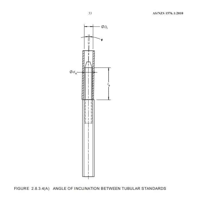
2.8.3.5 Inclinations between vertical components
Frame imperfection by angular deviations at the joints between vertical components shall be
taken in to account.
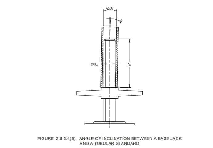
For a joint in a tubular component, the angle of inclination (ψ), either between a pair of
tubular components connected by a spigot permanently fixed to one of the components (see
Figure 2.8.3.4(A)) or between an adjustable baseplate and a tubular component (see
Figure 2.8.3.4(B)), may be calculated from the following equation:
o o i tan
l d D − ψ = . . . 2.8.3.4(1)
where
tan ψ = not less than 0.01
Di = nominal inner diameter of the tubular standard
do = nominal outer diameter of the spigot or base jack
lo = nominal overlap length
ψ = see Figure 2.8.3.4(A) and Figure 2.8.3.4(B) respectively
When there are a number (n) of standards with such joints side by side and when planned
pre-deflections are excluded from the value for ψ, represented by ψn, may be calculated
from the following equation:

where
tan ψ is given in Equation 2.8.3.4(2) and n is greater than 2
The above applies to scaffolds where the length of the ledgers are not predetermined by
connecting devices (for example, for tube-and-coupler scaffolds).
In the case of a facade scaffold made of prefabricated component, the value of tan ψ for a
closed frame in its plane may be taken as 0.01 if the vertical overlap length is at least
150 mm; and as 0.015 if the overlap length is less.
2.8.4 Connection stiffness
The stiffness of a connection shall be assumed as zero (i.e. pin connection), unless
otherwise determined by test, and the results shall be documented.
2.8.5 Anchorage and tie assemblies
2.8.5.1 General
Where anchorage or tie systems, including guys, are used to stabilize the scaffold, their
design shall be such that neither the scaffold nor any building or supporting structure is
overloaded or damaged during normal use.
2.8.5.2 Location
Allowing for the requirement of Clause 3.7.4, the location of anchorage and tie systems
shall not obstruct clear access along the full length of any working platform or accessway.
2.8.5.3 Tie arrangement
Tie arrangement shall be designed and spaced vertically and horizontally to provide
stability and, as applicable, buckling restraints for the scaffold, taking into account the
strength of both the tie assembly and the supporting structure.
2.8.5.4 Drilled-in anchors
Drilled-in anchors, whether expanding or chemical types, that are subject to tensile loads
shall only be used where it is not practicable to secure or tie the scaffold in any other way.
Drilled-in anchors shall comply with the following requirements:
(a) An assessment of the material to which the drilled-in anchors are applied shall
confirm their suitability for the application.
(b) Expansion anchors subject to tensile loads shall be limited to the load-controlled
(torque-controlled) type, and the working load limit shall be lesser of the working
load limit specified by the anchor supplier or 65% of the ‘first slip load’ stated in the
supplier’s documentation, or 6 kN as required under Clause 2.5.3.2.
NOTES:
1 For the purpose of this Standard, an undercut type anchor is to be regarded as an
expansion anchor.
2 Installation of the expansion anchor requires that the anchors be installed in compliance
with the manufacturer’s recommended installation procedure so that the working load
limit can be achieved.
(c) Deformation-controlled anchors, including self-drilling anchors and drop-in (setting)
impact anchors shall not be used.
If the use of anchors specified in Item (c) is the only option for a specific application
or structure to which anchors will be connected to, then clear guidelines on design
(including load capacity) application and installation of the anchors to the supporting
media/structure to which it is being fixed to shall be obtained, and assessment of the
suitability of the supporting structure shall be obtained from the project engineer or
suitably qualified and experienced engineer familiar with such structures.
(d) Chemical anchors subject to tensile loads relying solely on chemical adhesion shall
have their working load limit determined by applying a reduction factor of 3.0 on the
average tensile component failure load, and shall be individually proof-tested to the
tensile working load limit prior to use.
C2.8.5 Ties are critical to the stability of a scaffold and the location of ties can
vary considerably from one project to another.
When considering scaffold tie patterns the following should be taken into account:
(a) A high scaffold may result in large self (dead) and imposed (live) loads
acting vertically, in addition to imposed (live) loads acting horizontally on
the lower standards of the installation, and consequently may require
additional ties at the lower levels to provide extra lateral restraint to the
standards. Horizontal imposed (live) loads can result from wind action on
containment sheeting.
(b) The top perimeter of a building may induce high wind actions and additional
ties may be required to stabilize the scaffold in this area.
(c) Adjacent buildings or structures may induce higher wind actions due to a
tunnelling effect.
(d) Brick walls may not be able to sustain the imposed lateral loads.
Some scaffold ties may not be able to be installed in the required positions. The
scaffold installation designer should then ensure that each tie that is to be
installed is able to sustain the additional load or it may be necessary to specify
additional ties to compensate.
2.8.6 Ropes and chains
2.8.6.1 Steel wire rope
Steel wire rope shall comply with AS 3569 or BS 302.2, as appropriate and, except where
used for lifting purposes, shall not be subjected to an imposed load that exceeds one-sixth
of the manufacturer’s guaranteed minimum breaking load of such rope. Termination of steel
wire ropes shall be in accordance with AS 2759.
2.8.6.2 Fibre rope
Fibre rope shall comply with AS 4142.2 or NZS/BS 2052, as appropriate, and shall not be subjected to an imposed load that exceeds one-tenth of the manufacturer’s guaranteed
minimum breaking load of such rope.
2.8.6.3 Steel chain
Steel chain shall comply with AS 2321, ISO 1835, ISO 1836, ISO 3075, ISO 3076 or
ISO 3077, as appropriate, and shall not be subjected to an imposed load that exceeds onesixth of the manufacturer’s guaranteed minimum breaking load of such chain.
2.9 SUPPORTING STRUCTURE
The scaffold shall be designed to ensure that the load placed on the supporting structure,
under the most adverse combination of actions applied to it by the scaffold, does not
adversely affect its structural integrity or the serviceability of the scaffold during the period of its use.
Where soleplates are used, they shall be designed to have sufficient strength and rigidity to distribute the load to the supporting structure.
Where necessary, the supporting structure shall be strengthened to ensure it has sufficient
strength and rigidity to accommodate the imposed loads.
NOTE: Provision may be required to prevent damage to the supporting structure.
COPYRIGHT
2.10 CHECK COUPLERS
The use of a check coupler shall not be considered to double the slip resistance of the
loadbearing coupler.
NOTE: For a test procedure to determine the capacity of a check coupler to resist slip along a tube, see AS/NZS 1576.2.
Part 3:Operational Requirements
3.1 SCOPE OF SECTION
This Section sets out the operational requirements of scaffolding and its associated
components, catch platforms, temporary stairways for general construction sites and the
relevant configurations.
3.2 ERECTION TOLERANCE
Erection of the scaffold shall be with a vertical tolerance that shall not exceed L/200, where
L is the height of the scaffold being erected.
3.3 SOLEPLATES
Where soleplates are required, they shall distribute the load from a scaffold to the
supporting structure without adversely affecting the structural integrity of the supporting
structure. Soleplates shall comply with the requirements of Clause 2.9.
NOTE: Soleplates may be required to prevent superficial damage to the supporting structure.
3.4 PLATFORMS
All platforms shall—
(a) be capable of supporting their design loads;
(b) be on a flat plane;
(c) be closely decked such that a gap between individual decking components in a bay is
not greater than 10 mm;
NOTE: This applies to platforms greater than 2 m above the ground.
(d) have a slip-resistant surface;
(e) be free of trip hazards;
(f) provide clear access past stacked materials;
(g) not be capable of uplift under working conditions; and
(h) not be capable of being dislodged by anticipated winds.
Scaffold planks shall comply with AS 1577 and, if manufactured from laminated veneer
lumber (LVL), shall also comply with the requirements of AS/NZS 4357.
Prefabricated platform units shall comply with AS/NZS 1576.3.
Boatswain’s chairs shall comply with AS 1576.4.
C3.4 Scaffold platforms need a slip-resistant surface to safeguard users from falls that
may result in injury. These include, for example, the use of captive planks or decking
units in prefabricate scaffolds, or planks of random length having sufficient mass to
remain stable and counteract the effect of overhang on putlogs or transoms when
stepped on by persons or loaded by the wheels of material transporters pushed along
the working platform.
There are several ways of ensuring that a platform will not be capable of uplift under
working conditions. These include, for example, the use of captive planks or decking
units in prefabricated scaffolds, or random planks of sufficient mass and length so that,
when they overhang their end putlogs by the distance necessary to prevent inadvertent
dislodgment, they will not become unstable when walked on or when loaded
wheelbarrows or trolleys are pushed along them. In circumstances, such as when short
planks are used, it may be necessary to secure planks to their supporting putlogs. This
can be achieved by tying planks down with flexible steel wire rope or purpose-designed
plank straps. Plank straps or fittings that incorporate protruding bolts and nuts should
be used only where they do not present a trip hazard, such as at the ends of the
platform. Steel fixing tie wire should not be used to secure planks.
Where the lapping of planks along the length of a platform is unavoidable, trip hazards
can be eliminated by fixing lengths of timber of the same thickness as the planks, cut at
a 45° angle, or fixing of purpose-designed rounded end pieces, at the ends of the lapped
planks.
At changes in the direction of a platform, lapped planks are acceptable without
additional measures. At such a point, users will be conscious that they are about to
change direction as they move from one run of the scaffold to another and, therefore,
are likely to be aware of changes in plank elevation at such change in direction.
Platforms may be exposed to the risk of dislodgment when they are on scaffolds subject
to extreme wind conditions such as at high altitudes, cyclonic seasons in tropical zones,
particularly high scaffolds or locations subject to wind funnelling as occurs within
high-rise precincts in major cities. In these situations, relying on the ‘tight fit’ of planks
or platform units will not be sufficient to ensure that they are not dislodged. Lashing of
planks or using plank straps to positively secure the platform are two methods that
could be used. Closely decked planking is used to prevent materials and small tools
from inadvertently falling through between the scaffold planks.
3.5 WORKING PLATFORM
A working platform shall—
(a) be arranged so as to provide a convenient working place to protect people from the
risk of falling and to retain materials and equipment;
(b) be of a width and length to enable the work to be carried out safely, allowing for
materials and tools that may be placed or used on the working platform and;
(c) comply with the dimensions in Clause 3.7.
Where materials are stored on a working platform, a clear and unobstructed access of not
less than 450 mm shall be maintained.
A top working platform on a birdcage shall not have any projections at the surface that may
cause a trip or other hazard.
3.6 BAY EXTENSION PLATFORM
3.6.1 General
Bay extension platforms shall not be fitted at the level of catch platforms, access platforms
or loading bays.
Bay extension platforms shall have nominal width dimensions not less than 220 mm nor
greater than 750 mm.
Bay extension platforms of nominal width less than 450 mm shall be located only at the
same level as the bay platform.
Bay extension platforms may be used for workers or as working platforms with only light
duty loading, as detailed in the installation design.
3.6.2 Location requirements of bay extension platforms
A bay extension platform may be placed adjacent to any bay at a lift height of the scaffold
provided such a bay is fully decked as a working platform, or appropriate edge protection is
provided to the bay extension.
Where a bay extension platform is positioned above or below the level of the adjacent bay
platform, it shall comply with the following requirements as applicable:
(a) The platform in the adjacent bay, whether above or below a bay extension platform,
shall be fully decked as a working platform and shall be fitted with external edge
protection.
(b) Where a bay extension platform is located not greater than 1 m above or below the
adjacent bay platform, edge protection is not required between the bay extension
platform and the adjacent bay platform. The lower adjacent bay platform shall be
provided with additional inside toeboards or equivalent edge protection. This shall
not prevent the installation of a toeboard to contain debris on the bay extension
platform.
(c) Where the bay extension platform is located not greater than 500 mm above or below
an adjacent fully decked bay platform, access is not required between the platforms.
(d) Where a bay extension platform is located greater than 500 mm above or below an
adjacent fully decked bay platform, suitable access shall be provided to the bay
extension platform from the adjacent bay platform.
The form access between the platforms shall take into account the distance between
the edge of the bay extension platform and adjacent working face (see Clause 3.9.8).
NOTE: The access marked in Figure 3.6.2 is diagrammatic only and is not intended to
represent an actual ladder.
(e) The bay extension platform may be located up to 1 m above or below an adjacent bay
platform. The next lower adjacent bay platform shall be fully decked and located not
greater than 2 m below the bay extension platform.
(f) Where a bay extension platform is located below a working platform such that the
next lower working platform is 2 m below the bay extension platform, additional
ledgers and/or transoms shall be installed within the bay at the level of the bay
extension platform.
NOTE: In prefabricated and frame systems, the distance between lifts is to be a nominal 2.0 m.
For diagrammatic representation of location of bay extension platforms, see Figures 3.6.2..
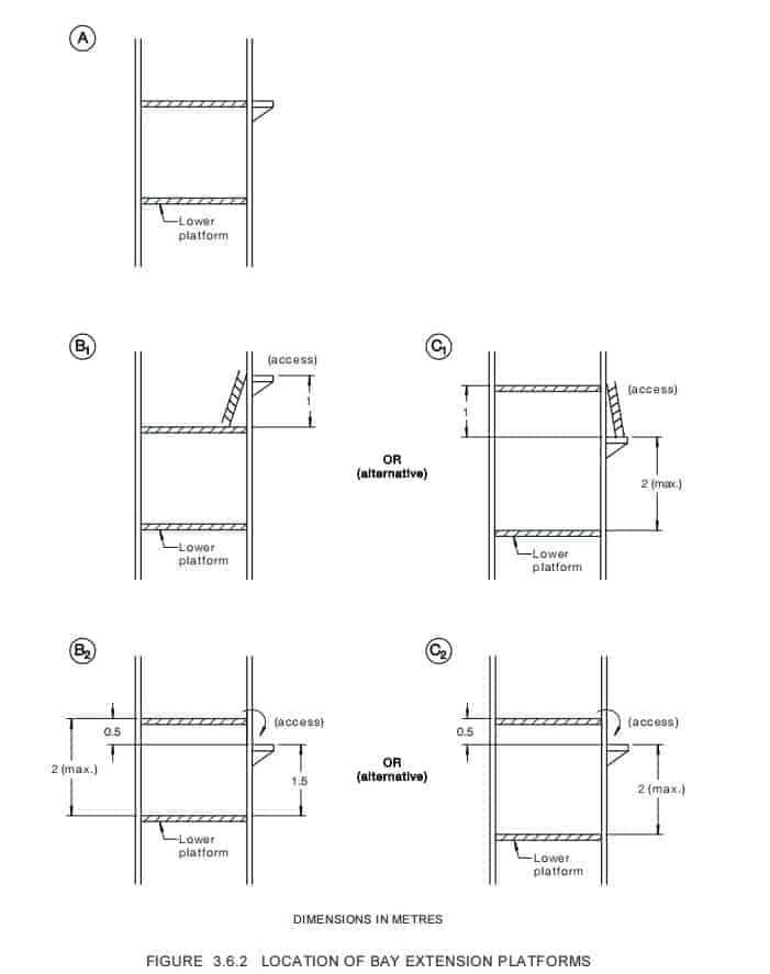
3.7.1 General bay dimensions for working platforms
The minimum unobstructed dimension of a working platform shall be not less than 450 mm,
regardless of the shape of the bay.
A clear access of not less than 450 mm shall be maintained on all platforms.
For New Zealand, the minimum bay dimension shall be 675 mm for all platforms.
3.7.2 Bay dimensions for duty-rated working platforms
3.7.2.1 General
The minimum bay dimensions containing a working platform shall be related to the type of
work that will be carried out on the working platform and shall be not less than the
dimensions specified in Clauses 3.7.2.1 to 3.7.4.
For New Zealand, the minimum bay dimension shall be 675 mm for all duty-rated working
platforms. A clear access of not less than 450 mm shall be maintained.
3.7.2.2 Light duty
The minimum bay dimension for a light duty working platform shall be 450 mm.
3.7.2.3 Medium duty
The minimum bay dimension for a medium duty working platform shall be 675 mm. Where
tools and materials will be placed on the working platform and the clear access cannot be
maintained, a bay extension platform of not less than 450 mm in width shall be added to
provide clear access.
3.7.2.4 Heavy duty
The minimum bay dimension for a heavy duty working platform shall be not less than
900 mm, or 675 mm where additional access is provided by a bay extension platform of not
less than 450 mm in width.
Where a heavy duty working platform is required for demolition work, a bay extension
platform shall not be added.
3.7.2.5 Special duty
The minimum bay dimension for a special duty working platform shall be sufficient to
provide a clear and unobstructed access of not less than 450 mm.
3.7.2.6 Boatswain’s chair
The seat of a boatswain’s chair shall be of sufficient dimensions to comfortably
accommodate the occupant.
3.7.3 Dimensions for access platform
The clear width of an access platform shall be not less than—
(a) 450 mm for persons and hand tools only;
(b) 675 mm for persons and materials; and
(c) 900 mm for emergency access.
3.7.4 Headroom
Clear headroom, measured above the surface of a working platform or access platform,
shall be a minimum of 1.85 m except where it is structurally or operationally impossible in
specific localized areas where it shall be a minimum of 1.72 m.
NOTE: Specific areas include those at transoms, lapped planks, plan bracing, tie tubes, and
similar areas.
3.7.5 Loading platform
A loading platform shall be of sufficient length and width for the materials and equipment
stored thereon. Clear access of not less than 450 mm in width shall be provided to access
such equipment.
3.8 SLOPE OF PLATFORMS
3.8.1 Working and closed platforms
All working platforms and closed platforms shall be erected level with a nominal tolerance
of 3° in all directions, unless otherwise specifically designed.
3.8.2 Access platform
The transverse slope shall not exceed 3°.
The longitudinal slope shall not exceed 20°. Where the longitudinal slope is greater than 7°
from the horizontal, it shall incorporate slip restraint. Slip restraint shall be of a similar
performance level that can be achieved by the use of cleats that are—
(a) nominally 25 mm thick;
(b) nominally 50 mm wide;
(c) spaced at intervals of nominally 450 mm;
(d) securely fixed to the upper surface of the platform; and
(e) the full width of the platform other than a 100 mm wide gap for a wheel of a material
transporter, if required.
3.9 CATCH PLATFORMS
A catch platform shall satisfy the following requirements:
(a) The cantilevered portion of the platform shall be at an angle sufficient for the
intended task.
(b) The platform shall be closely decked to prevent materials falling through.
(c) The minimum dimensions shall be sufficient for the intended task.
(d) The scaffold design shall be such that debris expected to be caught on a catch
platform shall not destabilize the scaffold.
(e) The platform decking shall not be capable of dislodgement under environmental or
working conditions.
(f) The platform shall be constructed to contain falling material. A catch platform shall
not be used as an accessway.
(g) If persons are required to access catch platforms, edge protection shall be provided.
3.10 EDGE PROTECTION
3.10.1 General
Except where Clauses 3.10.3, 3.10.4 or 3.11.1(c) apply, edge protection shall be provided at
the open sides and ends of all platforms, landings and along temporary stairways from
which a person or object could fall a distance exceeding 2 m.
NOTE: Legislation of a State, Territory of Australia or legislation in New Zealand may specify a
different fall distance
The working platform shall be placed as close as practicable to the working face to reduce
the risk of people or materials falling between the gap of the working face and working
platform.
Temporary stairways shall be provided with handrails as specified in Clauses 3.11.3.1(g)
and 3.11.3.1(h).
C3.10.1 Even though a working platform may be positioned less than 2 m above the
surface on which the scaffold is positioned, the platform may be adjacent to the edge of
a slab, a void or other place where the distance from which a person could fall is
greater than 2 m, in which case edge protection will need to be provided at the affected
edge of the platform. People can be injured from falls of less than 2 m, particularly
when hazards, such as exposed vertical steel reinforcement, exist adjacent to the
platform, and edge protection may have to be provided based on the results of the risk
assessment.
3.10.2 Forms of edge protection
3.10.2.1 General
Edge protection shall comprise of one of the following:
(a) Guardrails, midrails and toeboards.
(b) Guardrail panels.
(c) Guardrails and infill panels.
NOTE: Cross-braces on frame scaffolding do not satisfy the requirements for edge protection.
Edge protection shall be provided for all temporary stairways in accordance with
Clause 3.11.3.
3.10.2.2 Guardrails
Guardrails shall comply with the following requirements:
(a) They shall be set at a height of not less than 900 mm above the platform.
NOTE: Where the scaffold provides edge protection for a higher adjacent surface, increased
height of guardrails may be required [see Figure 3.10.4(B)].
(b) They shall be set parallel to the platform.
(c) They shall be set not more than 100 mm outside the edge of the platform.
(d) Flexible materials such as ropes and chains shall not be used.
3.10.2.3 Midrails
Midrails shall comply with the following requirements:
(a) They shall be positioned such that the maximum vertical gap between adjacent
horizontal edge protection components shall not exceed 500 mm.
NOTE: It may be necessary to provide more than one midrail.
(b) They shall be set parallel to the platform.
(c) They shall be set not more than 100 mm outside the edge of the platform.
(d) Flexible materials, such as ropes and chains, shall not be used.
3.10.2.4 Toeboards
Toeboards shall comply with the following requirements:
(a) They shall extend not less than 150 mm above the working platform surface.
(b) They shall be securely attached to the scaffold.
(c) The vertical gap between the toeboard and the platform shall not exceed 10 mm.
(d) The horizontal gap between the toeboard and the platform shall not exceed 10 mm.
3.10.2.5 Panels
Guardrail panels and infill panels shall comply with the following requirements:
(a) They shall be securely fixed parallel to the platform.
(b) They shall extend not less than 900 mm above the platform.
(c) They shall be nominally vertical.
(d) They shall incorporate a kick plate that extends not less than 150 mm above the
platform, unless a separate toeboard is provided.
(e) The horizontal or vertical gap between the kick plate and the platform shall not
exceed 10 mm.
(f) The top or exposed edges of panels shall be free of sharp edges, points, etc. (which
may cause injury).
3.10.3 Openings in edge protection
Openings in edge protection at points of access to stairways or ladders shall be adequately
protected with gates, or shall be sufficiently distant from working platforms to prevent
persons working on such platforms from inadvertently falling through the opening. Gates
shall be self-closing and shall not open away from the platform. Gates shall be designed and
located to adequately perform the function of the replaced guardrail.
Where a gap is temporarily exposed to allow work to proceed, such as loading of materials,
cladding, rendering, window fixing, it shall be closed up as soon as practicable.
3.10.4 Omission of edge protection
3.10.4.1 From a platform adjacent to the face of a building
Edge protection or components of edge protection may be omitted from a platform or
landing adjacent to the face of a building or structure, provided such face—
(a) has strength and rigidity not less than those of the omitted components;
(b) is located at the required height of the omitted components above the surface of the
platform;
(c) in all other respects perform the function of the omitted components; and
(d) the resultant gap between the face and the platform edge or adjacent horizontal
member of the scaffold does not exceed—
(i) 225 mm (or 300 mm in New Zealand) where the face is a working face; or
(ii) 100 mm where the face is not a working face.
3.10.4.2 From a platform adjacent to the floor of a building
Edge protection or components of edge protection may be omitted from a platform or
landing adjacent to the floor of a building or structure, provided the following conditions
are met:
(a) The floor is not greater than 225 mm horizontally distant from the platform edge
where the platform is adjacent to a working face; or the floor is not greater than
100 mm horizontally distant from the platform edge where the platform is not
adjacent to a working face.
(b) The floor has its upper surface not greater than 300 mm vertically below the surface
of the platform [see Figure 3.10.4(A)]; or the soffit of the floor or dropdown beam is
not greater than 300 mm vertically above the surface of the platform [see
Figure 3.10.4(B)].
3.10.4.3 New Zealand only
In New Zealand, where containment sheeting is fitted, toeboards and kick plates may be
omitted from landings.
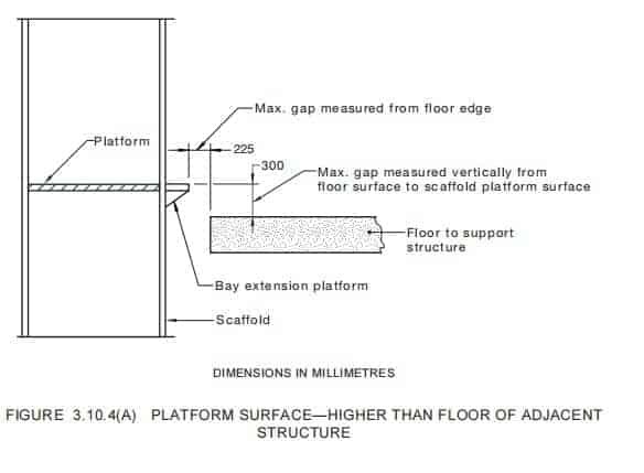
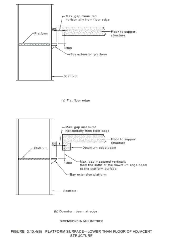
Where equipment or materials are intended to be deposited on a working platform to a
height exceeding the height of the toeboard and there is any likelihood of such materials or
equipment falling or being knocked from the platform, additional edge protection shall be
provided. Such additional edge protection may be achieved by—
(a) higher toeboards;
(b) securely fixed chain wire mesh complying with AS 2423 with a maximum aperture of
60 mm × 60 mm, and a minimum wire diameter of 2.0 mm with a minimum tensile
strength of 380 MPa, or better performance;
(c) guardrailing panels incorporating mesh; or
(d) infill panels incorporating mesh.
NOTE: Steel wire mesh used in panels should have apertures not exceeding 50 mm × 50 mm
where wire of not less than 4.0 mm diameter is used; or have apertures not exceeding
50 mm × 25 mm where wire of not less than 2.5 mm diameter is used. Where the materials to be
contained are smaller than the apertures given above, consideration should be given to using a
mesh with smaller apertures or providing a lining.
3.11 ACCESS
3.11.1 General
Safe access to and from working platforms shall be provided. Such access shall take the
form of temporary stairways, access platforms, ladders or other suitable means. The
following requirements apply to access to and from working platforms:
(a) Access openings and stairways shall be free of sharp edges and points that could
cause injury while accessing the platform.
(b) Openings in edge protection at points of access to stairways or ladders shall comply
with Clause 3.10.3.
(c) Where an opening is located in a platform for a ladder access or a stair access, the
opening shall be sufficiently distant from the working platform or shall be provided
with a means to prevent persons falling through the opening.
NOTE: Suitable means include trapdoors, edge protection, gates or an appropriate
combination of these.
(d) Trapdoors shall not require a person to hold the trapdoor open whilst passing through
the opening.
(e) Gates shall be self-closing and shall not open away from the platform. Gates shall be
designed and located to adequately perform the function of a guardrail.
NOTES:
1 ‘Other means’ of access may include, for example, direct access to the platform from an
adjoining floor, stairway or fixed platform of the building or structure, provided it is at
nominally the same level and any gap between the floor and the edge of the platform is not
sufficiently wide to present a trap or tripping hazard [see also Clause 3.10.4.1(d)(ii)].
Where mechanical means of access is provided, such as a personnel and materials hoist,
alternate non-mechanical means of safe egress should also be provided, such as a stair or
ladder tower, so that, in the event of an emergency or mechanical breakdown, the scaffold
users can promptly and safely exit the scaffold.
2 Ladder access may be used where access to the working platform is needed only by a few
persons and where small tools and materials are contained within a tool belt or pouch. Other
tools, equipment and materials should be delivered separately to the working platform.
3.11.2 Minor scaffold access
3.11.2.1 General
Access to the working platform of a minor scaffold may be by means of a temporary
stairway, ladder or by climbing the end frames of the scaffold.
3.11.2.2 Access in the form of temporary stairway or ladder
Where access takes the form of a temporary stairway or ladder, the access shall comply
with the following:
(a) At the location of points of access to stairways or ladders on the minor scaffolds, a
person shall not be required to climb over the guardrailing or through the
guardrailing, to gain access to the platform.
(b) The means of access shall not destabilize the scaffold.
(c) Trapdoors shall not be used as access where the platform height of a minor scaffold
does not exceed 1.5 m above the supporting structure.
(d) Treads and rungs shall be of size and cross-sectional shape adequate to comply with
the requirements for ladders specified in AS/NZS 1892.1.
3.11.2.3 Access by climbing end frames
Where access is by climbing the end frames the access shall comply with the following:
(a) Access shall be by climbing on the outside of the scaffold end frames using horizontal
members.
(b) This form of access shall not destabilize the minor scaffold during climbing or whilst
accessing the working platform.
(c) The horizontal members of the end frames shall be of equal spacing and not be
greater than 400 mm apart.
(d) The horizontal members shall be capable of supporting a concentrated load of not less
than 300 kg at the centre of the span without permanent deformation.
(e) A person shall not be required to climb over or through the end frames or guardrailing
to gain access to the working platform. The highest end frame may be fitted with a
self-closing gate or similar device for edge protection.
3.11.3 Temporary stairways
3.11.3.1 Temporary stairways for scaffolding and general construction site access
Where temporary stairways are used, they shall comply with the following:
(a) Stairways shall be in straight flights and of a tread width not less than 500 mm wide
and a tread depth (TD) of not less than 175 mm.
(b) The number of rises in any flight of stairs shall not exceed 18. Where there is more
than one flight in the same direction, a landing shall be used between flights.
(c) Where there is a change in direction between flights, a landing shall be used.
(d) The surface of every tread shall extend across the full effective width of the stairway
and the tread surface shall be slip resistant.
(e) The minimum vertical clearance for stairs shall be not less than 1850 mm.
(f) The minimum vertical clearance for landings shall be not less than 1850 mm.
(g) All rises and all goings, in the same flight of stairs, shall be of uniform dimensions
within a tolerance of ±5 mm for prefabricated systems and 10 mm tolerance between
consecutive treads in site-constructed systems.
NOTE: In some cases it may be necessary to modify the landing at the base of the stairway to
achieve uniformity in the rises.
(h) A rise (R) shall be not less than 150 mm and not greater than 225 mm.
(i) The going (G) shall not be less than 175 mm or greater than 355 mm and shall be not
greater then the actual tread depth plus a maximum gap of 30 mm between the rear
edge of one tread and the nosing of the tread above.
(j) The combination of twice the rise plus the going (2R + G) shall be not less than
540 mm, and not greater than 700 mm. (i.e. 540 ≤2R ± G ≤700).
C3.11.3.1(i)(j)(k) Not all combinations of rise and going within the ranges
specified in Items (i) and (j) will comply wit the requirements of Item (k). It will be
necessary for the designer to ensure that the stairway complies with the
combination range limitation detailed in Item (k) and as illustrated in
Figure 3.11.3.
(k) The length of a landing in the direction of travel shall be not less than 400 mm and
the width shall be not less than the width of the stairway.
(l) Every access landing shall provide standing space of at least 400 mm clear of crosstraffic or gate swing.
(m) Each stairway shall be provided with handrails. The external handrail shall extend for
the length of each stairway flight or shall consist of a number of horizontal or
inclined members with a maximum vertical spacing of 500 mm. For each stairway
flight, the internal handrail shall be continuous and shall extend at least two-thirds of
the length of the flight. Where a person could fall a distance greater than 2 m from a
stairway and horizontal members are not present, midrails complying with
Clause 3.10.2.3 shall be installed. External edge protection may take the form of
handrail panels provided the openings between vertical balusters are not greater than
125 mm apart, measured horizontally.
NOTE: Horizontal members of the scaffold structure may form part of external handrail.
(n) The handrail shall be supported so as to allow unrestricted movement of the hand
along the upper surface between support points.
(o) Except in New Zealand stairway landings shall be provided with edge protection
adjacent to their open sides and ends. Where containment sheeting is provided,
toeboards may be omitted.
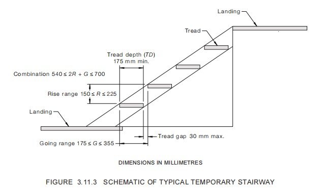
Where temporary stairways for stretcher access are constructed from scaffolding equipment
they shall comply with Clause 3.11.3.1, except for the following:
(a) The stairway angle of slope to the horizontal shall be not greater than 45°.
(b) The length of a landing in the direction of travel shall be not less than 1200 mm and
the width not less than the width of the stairway.
(c) The upper surface of the external handrail shall be not less than 1400 mm above the
landing or top of each stair tread.
3.11.4 Handrails
Handrails shall be provided to access platforms or those parts greater than 1 m above the
supporting surface. Where a person could fall a distance greater than 2 m from an access
platform, midrails complying with Clause 3.10.2.3 shall be installed.
Handrails for access platforms shall comply with the following requirements:
(a) The upper surface of the handrail shall be set at a height of not less than 900 mm not
more than 1100 mm above the platform.
(b) Flexible materials such as ropes and chains shall not be used.
(c) They shall be set parallel to the platform.
(d) They shall be set not more than 100 mm outside the edge of the platform.
3.11.5 Portable ladders
Ladders fixed to a scaffold shall not adversely affect the stability of the scaffold.
Access to a platform on the scaffold from the external ladder shall be unobstructed and
shall not require persons to climb over or through the guardrailing.
Where portable ladders are used, they shall be single or extension ladders and shall comply
with the industrial-duty requirements of AS/NZS 1892.1, AS 1892.2, AS/NZS 1892.3 and
AS/NZS 1892.4. Additional portable ladders shall comply with the following:
(a) Where ladders are supported by scaffold framework (typically by hooks and ladder
stand-off arms), the length of the cantilevered section (below the stand-off arms) shall
not exceed one quarter of the overall length of the ladder.
(b) Where extension ladders are used, they shall be specifically designed to be supported
by scaffold framework with appropriate consideration to the operation of the latching
device.
(c) Ladders shall be pitched at a slope of not less than one horizontally to four vertically
and not greater than one horizontally to six vertically.
(d) Ladders shall be secured to prevent displacement at the base and head.
(e) Unless the ladder is supported by the scaffold framework it shall be based on firm
level ground or on a solid structure or a ladder landing.
(f) The maximum step height from the supporting surface or ladder landing (as
appropriate) to the lowest rung of the ladder shall not exceed 400 mm.
(g) Openings in working platforms for ladders shall be as small as practicable and shall
be adequately guarded in accordance with Clause 3.10.3 or a trapdoor shall be
provided over the opening.
(h) The base of a ladder shall be offset from the head of the ladder below, to ensure more
ladders do not take the form of a single continuous ladder.
(i) Ladders shall extend a minimum of 900 mm in Australia and 1000 mm in New
Zealand above the landing or top departure point, or other suitable hand-holds shall
be available continuing up to that height.
(j) There shall be clear and unobstructed access to and from ladders to each landing.
(k) Ladders on mobile scaffolds shall be clear of the scaffold supporting surface.
(l) The maximum height between successive landings, serviced by a portable ladder,
shall not exceed 4 m or two lifts, whichever is the greater.
3.12 ADDITIONAL REQUIREMENTS FOR MOBILE SCAFFOLDS
3.12.1 Castors
Castors shall comply with AS/NZS 1576.2 and shall be capable of being locked when work
is being performed from the scaffold.
3.12.2 Other wheels
Pneumatic tyres may be used to relocate the scaffold. Such tyres shall not be used when
work is being performed from the scaffold.
3.12.3 Supporting structure
The supporting structure of a mobile scaffold shall be a hard flat surface.
Unless the castors incorporate adjustable legs, the surface shall be level.
Where the castors incorporate adjustable legs, the gradient of the surface shall not exceed
5°, unless provision is made to take the load off the castors during use of the scaffold.
3.12.4 Additional bracing
Adequate bracing in the horizontal plane shall be provided to prevent distortion of the
scaffold while it is being moved.
3.12.5 Movement of mobile scaffolds
A mobile scaffold shall not be moved or relocated unless the scaffold is unoccupied and all
items on the scaffold are secured against falling.
NOTE: For design requirements for mobile scaffolds being moved other than manually, see
Clause 2.5.3.3.4.
3.13 ADDITIONAL REQUIREMENTS FOR MINOR SCAFFOLDS
3.13.1 General
The platform of a minor scaffold shall be supported above the supporting structure by one
or a combination of the following:
(a) Fixed frames.
(b) Folding frames.
(c) Modular prefabricated components.
3.13.2 Fixed frame minor scaffold
A fixed frame minor scaffold is where the joints in the frames of a minor scaffold are fixed
through welding, riveting or similar type connections and where the structure is not
designed to be dismantled for transport or storage between applications.
3.13.3 Folding frame minor scaffold
A folding frame minor scaffold is where a number of joints in the frame of a minor scaffold
are connected through hinged, sliding or similar type connections and where the structure is
designed to be fully or partially collapsed to reduce its size for transport or storage between
applications.
3.13.4 Prefabricated minor scaffold
A prefabricated minor scaffold is where the structure of the minor scaffold comprises of
standards, ledgers, transoms, connectors or similar type components and is designed to be
fully dismantled for transport or storage between applications.
3.14 MINOR SCAFFOLD SUPPORTS
3.14.1 General
The base frame of a minor scaffold shall be designed to prevent damage to surfaces on
which the minor scaffold is used. The base of a minor scaffold may incorporate a member
whose length rests on the supporting surface. Alternatively, the base frame may incorporate
footplates fixed to the bottom end of each of the vertical members.
3.14.2 Footplate on a minor scaffold
The footplate on a minor scaffold shall comply with the following:
(a) Where designed to be used only internally or on hard supporting surface, such as
concrete, the projected area of a minor scaffold footplate shall be not less than
25 mm × 25 mm.
(b) Where designed to be used externally on what could potentially be a soft supporting
surface, a footplate shall have a minimum base dimension not less than
50 mm × 50 mm.
(c) Where the supporting surface is not able to adequately support the fully loaded minor
scaffold, without differential settlement, soleplates shall be used.
NOTE: The manufacturer will mark the minor scaffold to reflect these requirements.’
3.15 STABILITY AND RIGIDITY OF A MINOR SCAFFOLD
3.15.1 Platform proportions
To assist in achieving stability against overturning on a minor scaffold, the maximum
platform height above the supporting structure shall not exceed 2 times the minimum base
dimension, with an absolute maximum height of 2 m.
3.15.2 Resistance to collapse
Once erected, the assembled structure including the platform legs, standards or frame of a
minor scaffold shall remain fixed in that assembled form until dismantled. The movement
of persons on a minor scaffold shall not be capable of collapsing the scaffold, where the
amount of movement is appropriate for the activity of work for which that minor scaffold is
designed.
3.16 WHEELED MOVEMENT OF UNLOADED MINOR SCAFFOLDS
3.16.1 General
Wheels other than those designed for a mobile scaffold may be used to transport or relocate
an unloaded minor scaffold. These wheels shall be located on the minor scaffold’s
componentry in a manner that shall not allow the minor scaffold to operate as a mobile
scaffold. The wheels shall not be capable of simultaneously taking both the dead and live
loads of an assembled minor scaffold.
3.16.2 Wheels to ease the transport of a disassembled minor scaffold
A whole minor scaffold or parts of a minor scaffold may be fitted with wheels to facilitate
the movement of the scaffold or part of its componentry, thereby reducing the potential for
manual handling of related injuries.
3.16.3 Wheels to relocate an assembled minor scaffold
As assembled minor scaffold may be fitted with wheels that are spring loaded in a manner
that will only take the weight of an unloaded minor scaffold. The spring-loaded wheels
shall only be used to relocate a fully assembled minor scaffold.
The spring-loaded castering wheels may be fitted to two or four of the platform legs or
standards and shall be adjusted to prevent minor scaffold movement when a person’s foot is
placed upon a ladder tread. The force applied to a tread to prevent movement of the minor
scaffold shall not exceed 150 N (15 kg).
3.17 COMPONENT MODIFICATION
Scaffolding components shall not be extended or otherwise modified unless the
modification has been designed by a competent person, the work is done by a competent
person, the resultant component complies with this Standard, and the modification is tested
or inspected and verified as being capable of meeting the intended performance criteria.
Prefabricated structural scaffold components and plain scaffold tube shall not be buttwelded on site within their length or have flame-cut ends.
3.18 TUBE EXTENSION
A tube shall extend past the coupler by not less than 10 mm.
APPENDIX A
MATERIALS AND DESIGN CONSIDERATIONS—GENERAL SCAFFOLDS
(Normative)
A1 GENERAL
The selection of materials shall take into account the strength, stiffness, durability and
ductility required to satisfy the design and operational requirements of this Standard.
A2 STEEL COMPONENTS
Steel components shall comply with AS 1163, AS 1444, AS 1594, AS 2074, AS 3678,
AS 3679.1, as appropriate.
Welded steel components shall comply with AS/NZS 1554.1.
A3 CAST IRON COMPONENTS
Cast iron components shall comply with AS 1831, AS 1832 or AS 1833, as appropriate.
A4 SURFACE FINISH OF CAST IRON AND STEEL COMPONENTS
A4.1 General
Surface finish may be one of the following:
(a) Galvanized, which shall be hot-dip galvanizing, in accordance with the requirements
for hollow sections of AS/NZS 4680.
(b) Components may be fabricated from steel tube that complies with any one of the
following:
(i) Electrogalvanized, internally and externally in accordance with the
requirements for hollow sections of not less than coating class ZE100/100 of
AS/NZS 4750.
(ii) Hot-dip galvanized, internally and externally, in accordance with the
requirements for hollow sections of not less than coating class HDG200 of
AS/NZS 4792.
(iii) Produced from pre-galvanized strip of not less than coating class ZB100/100 of
AS/NZS 4792.
(c) Notwithstanding that components have been hot-dip galvanized in accordance with
Item (a) above or fabricated from steel tube treated in accordance with Item (b)
above, the external surface may be painted with an identification colour.
(d) Black (uncoated).
(e) Other coatings.
NOTE: It will be necessary for the purchaser to state in the order or enquiry what type of surface
finish is required and whether galvanizing is to be internal and external or external only.
A5 STEEL TUBE
A5.1 General
Steel tube shall be manufactured by the electric resistance weld process (ERW). It shall
have a minimum yield strength of not less than 250 MPa and shall comply with AS 1163.
A5.2 Thin-walled fully or partly open-ended hollow sections
Thin-walled fully or partly open-ended hollow sections of wall thickness 3.2 mm or less
shall be hot-dip galvanized internally and externally in accordance with the requirements
for hollow sections of AS/NZS 4680.
For secondary structural members such as ledgers, braces and similar components,
pre-galvanized tube of wall thickness 3.2 mm may be used provided all heat-affected weld
zones are protected by suitable anti-corrosion protection applied after cooling down
following completion of welding operations.
CA5.2 Hot-dip galvanizing is recommended for all open-ended hollow sections,
regardless of the wall thickness, to reduce internal corrosion during the working life of
the component. In some industries, galvanized components are not permitted because of
the adverse effects of zinc (e.g. in power station boilers).
Fabricated components where the ends have been fully closed by welding do not have to
comply with the requirement for hot-dip galvanizing.
Notwithstanding that hollow sections have been hot-dip galvanized, the external surface
may be painted with an identification colour.
A5.3 Tube diameters for tube-and-coupler scaffolding
The nominal outside diameter of steel tube used for tube-and-coupler scaffolding shall be—
(a) 48.3 mm;
(b) less than 45 mm; or
(c) greater than 55 mm.
In New Zealand the nominal outside diameter of steel tube shall be not less than 48.3 mm.
CA5.3 Nominal outside diameters specified in Items (b) and (c) are set to permit the
use of tubes to enable a performance-based design. The limitations have been set for
these tubes to ensure the outside diameters are sufficiently different from 48.3 mm
because scaffold couplers designed and tested for the standard 48.3 mm outside
diameter tube when used on tubes of these outside diameters will not meet the
performance requirements of AS/NZS 1576.2. Where tubes with outside diameters that
comply with Items (b) and (c) above are used, it will be necessary to specifically design
couplers for selected outside diameters.
A5.4 Tube outside diameter used for prefabrication scaffolding
The main structural members that require the use of scaffold couplers for ties or other
structural purposes shall comply with Paragraph B5.3.
A5.5 Internal projections
Internal projections shall not exceed 1.2 mm.
NOTES:
1 Internal projections include the weld upset produced by the electric resistance welding
process.
2 Where components manufactured for such tube are hot-dip galvanized after fabrication, the
internal projection may increase in size and interfere with the proper fit of other components
that have to be inserted into the tube (e.g. spigots and adjustable bases). It may be necessary
for the manufacturer to specify a lesser internal projection than the specified maximum from
the tube supplier.
A5.6 End finish
The bearing ends of steel tube shall be cut cleanly and square with the axis of the tube. Any
bevel trimming of tube ends shall leave a minimum end-face bearing width of not less than
the equivalent of 80% of the nominal wall thickness.
A6 ALUMINIUM
A6.1 Cast components
Components shall be made from cast aluminium alloys that comply with AS/NZS 1874.
The 700 series alloys shall not be used.
NOTE: Pressure die-casting is not recommended as a method of manufacture for primary
loadbearing members. Where pressure die-casting is used, the component design should include
sufficient redundancy to compensate for potential reduction in capacity due to the possibility of
high internal porosity within the component.
A6.2 Wrought components
Components shall be made from wrought aluminium alloys that comply with AS 1866 for
extrusions or AS 1734 for sheet and plate.
The 2000 and 7000 series alloys shall not be used.
Welded components shall comply with the requirements of AS/NZS 1665 and
AS/NZS 1554.1.
A6.3 Tube properties for tube-and-coupler scaffolding
Aluminium tube for tube-and-coupler scaffolding shall have the following minimum
properties:
(a) Tensile strength …………………………………260 MPa.
(b) 0.2% proof stress…………………………………240 MPa.
(c) Elongation on 50 mm gauge length…………………………………8%.
A6.4 Tube outside diameters
A6.4.1 Tube outside diameter for tube and coupler scaffolding
The nominal outside diameter of tube used for tube-and-coupler scaffolding shall be—
(a) 48.4 mm;
(b) 50.8 mm;
(c) less than 45 mm; or
(d) greater than 55 mm.
NOTE: See Commentary CA5.3 for explanations.
A6.4.2 Tube used for prefabricated scaffolding
The main structural members that require the use of couplers for ties or other structural
purposes shall comply with Paragraph A6.4.1.
A6.4.3 End finish
The bearing ends of aluminium tube shall be cut cleanly and square with the axis of the tube
and shall not be bevel trimmed.
A7 COUPLERS AND ACCESSORIES
Couplers and accessories shall comply with AS/NZS 1576.2.
A8 STRUCTURAL PLYWOOD
Structural plywood shall comply with the requirements of AS/NZS 2269.
A9 INSPECTION, REPAIR AND MAINTENANCE
The following apply to the inspection, repair and maintenance of scaffolds:
(a) Scaffold tubes of steel or aluminium or tubular components of prefabricated modular
scaffolding having a surface deformation exceeding 4 mm, or with a cross-sectional
distortion exceeding 1.03 times the diameter of the undistorted cross-sectional, shall
have been reduced in length to remove the distorted section or be scrapped if
shortening is not practicable.
(b) Scaffold tubes of steel or aluminium that are bent (i.e. out of straight), so that any
section of the tube is greater than 1/300 of the length of the tube from the alignment
between the ends of the tube (e.g. as determined by a string line stretched between the
ends), shall be reduced in length or be scrapped if shortening is not practicable.
(c) Tubular components of prefabricated modular scaffolding that are lightly bent (less
than 15 mm/m length) shall be straightened. If it is not practicable to straighten the
component it shall be scrapped.
(d) Tubular components of prefabricated modular scaffolding that are severely bent, shall
be shortened (where practicable) to the next smaller size by cutting off the damaged
part and refixing a new end connection. If it is not practicable to shorten the
component it shall be scrapped.
(e) Prefabricated modular scaffolding components, such as ledger, transoms, braces and
similar components that have damaged end attachments, shall not be used.
APPENDIX B
MATERIALS, DESIGN CONSIDERATIONS AND MANUFACTURE—MINOR
SCAFFOLDS
(Normative)
B1 GENERAL
The selection of materials shall take into account the strength, stiffness, durability and
rigidity required to satisfy the design and operational requirements of this Standard with
particular reference to minor scaffolds.
B2 STEEL COMPONENTS
Steel shall comply with Paragraph B2, Appendix B.
B3 CAST IRON COMPONENTS
Cast iron components shall comply with Paragraph B3, Appendix B.
B4 STEEL TUBE
Steel tube shall be manufactured by the electric resistance weld process ((ERW), have a
minimum yield strength of not less than 250 MPa and comply with AS 1163.
Steel tube may be formed from black steel strip or may be formed from steel strip hot-dip
galvanized by a continuous or specialized process in accordance with AS/NZS 4792.
B5 SURFACE FINISH CAST IRON AND STEEL COMPONENTS
Types of surface finish shall include the following:
(a) Galvanized Components galvanized after fabrication shall be hot-dip galvanized in
accordance with AS/NZS 4680. Open-ended hollow sections shall be hot-dip
galvanized internally and externally.
(b) Other coatings Open-ended hollow sections shall have other finishes applied
internally and externally.
B6 ALUMINIUM COMPONENTS
B6.1 Cast aluminum
Cast aluminum components shall comply with Paragraph A6.1, Appendix A.
B6.2 Wrought aluminium
Wrought aluminium components shall comply with Paragraph A6.2, Appendix A.
B7 MANUFACTURING
B7.1 Sharp edges
Minor scaffolds shall have no unfinished sheared metal edges or other sharp parts that are
exposed to hands or legs. Sheared metal edges that are not rolled shall be finished to
remove any sharp feathering, edges, burrs or spurs caused by a shearing or cutting process.
B7.2 Fixings
Bolt and rivet holes shall be accurately located and within accepted standards for the
material used. Rivets shall be properly set and free from structural defects.
B7.3 Welds
Welds shall be in accordance with the accepted standards for the material used (that is,
AS/NZS 1665 for aluminium, and AS 1554.1 or NZS 4704 for steel). Weld splatter and slag
that cause interference with proper fit of components shall be removed. All weld spatter and
slag on external surfaces shall be removed prior to application of any surface finish.
APPENDIX C
FLOWCHART FOR DESIGN OF NEW COMPONENTS OR A GROUP OF
COMPONENTS
(Informative)
Figure C1 provides an example of a flow chart for the design of new individual components
or a group of new components which, when combined, will form a new prefabricated
scaffold system.
NOTE: AS/NZS 1576.3:1995 has not been revised at date of publication of this Standard and
accordingly references below may not fully align with the requirements of this Standard.
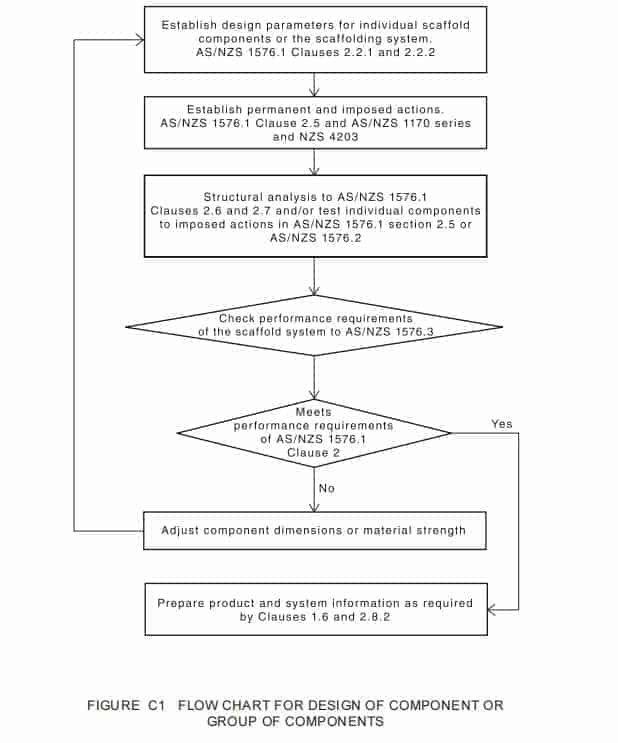
FLOWCHART FOR STRUCTURAL DESIGN CHECK OF A SCAFFOLD
(Informative)
Figure D1 provides an example of a flowchart for a scaffold design check, which may be
used to ensure that proposed or erected scaffold complies with relevant structural
requirements of AS/NZS 1576.1. It may also be used to verify or check that an erected
scaffold complies with its design. The suggested methodology for the design check is a
general one and does not cover all individual components of scaffolding or all the
combinations that these components can be used in. Furthermore, the following considers
that the working load limits for the particular scaffold have been established through prior
structural analysis and/or testing.
NOTE: AS/NZS 1576.3:1995 has not been revised at date of publication of this Standard and
accordingly references below may not fully align with the requirements of this Standard.
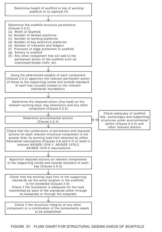
AS
1418 Cranes, hoists and winches
1418.10(Int) Part 10: Elevating work platforms
1418.16 Part 16: Cranes (including hoists and winches)—Mast climbing work
platforms
3610 Formwork for concrete
AS/NZS
1576 Scaffolding
1576.5 Part 5: Prefabricated splitheads and trestles
Standards Australia
Standards Australia is an independent company, limited by guarantee, which prepares and publishes
most of the voluntary technical and commercial standards used in Australia. These standards are
developed through an open process of consultation and consensus, in which all interested parties are
invited to participate. Through a Memorandum of Understanding with the Commonwealth
government, Standards Australia is recognized as Australia’s peak national standards body.
Standards New Zealand
The first national Standards organization was created in New Zealand in 1932. The Standards
Council of New Zealand is the national authority responsible for the production of Standards.
Standards New Zealand is the trading arm of the Standards Council established under the Standards
Act 1988.
Australian/New Zealand Standards
Under a Memorandum of Understanding between Standards Australia and Standards New Zealand,
Australian/New Zealand Standards are prepared by committees of experts from industry,
governments, consumers and other sectors. The requirements or recommendations contained
in published Standards are a consensus of the views of representative interests and also take
account of comments received from other sources. They reflect the latest scientific and industry
experience. Australian/New Zealand Standards are kept under continuous review after publication
and are updated regularly to take account of changing technology.
International Involvement
Standards Australia and Standards New Zealand are responsible for ensuring that the Australian
and New Zealand viewpoints are considered in the formulation of international Standards and that
the latest international experience is incorporated in national and Joint Standards. This role is vital
in assisting local industry to compete in international markets. Both organizations are the national
members of ISO (the International Organization for Standardization) and IEC (the International
Electrotechnical Commission).
Visit our web sites
www.standards.org.au www.standards.co.nz
www.standards.com.au