- Part 1: Scaffolds — Performance requirements and general design
1 Scope
This European Standard specifies performance requirements and methods of structural and general design for
access and working scaffolds, referred to from hereon as working scaffolds. Requirements given are for scaffold
structures, which rely on the adjacent structures for stability. In general these requirements also apply to other
types of working scaffolds. Normal requirements are set down, but there is also provision for special cases.
This European Standard also specifies structural design rules when certain materials are used and general rules
for prefabricated equipment.
The standard excludes:
platforms suspended by ropes, whether fixed or movable;
horizontally movable platforms including Mobile Access Towers (MAT);
power-operated platforms;
scaffolds used as protection for roof work;
temporary roofs.
NOTE 1 Most working scaffolds are formed from prefabricated components or from tubes and couplers. Some examples of
working scaffolds are façade scaffolds, static towers, and birdcage scaffolds, but details are not given for all of these.
NOTE 2 Falsework and shoring may be made of the structural components described in this standard, but are not working
scaffolds.
NOTE 3 Particular requirements for façade scaffolds made of prefabricated components are specified in EN 12810 -1 and
EN 12810-2.
2 Normative references
This European Standard incorporates by dated or undated reference, provisions from other publications. These
normative references are cited at the appropriate places in the text and the publications are listed hereafter. For
dated references, subsequent amendments to or revisions of any of these publications apply to this European
Standard only when incorporated in it by amendment or revision. For undated references, the latest edition of the
publication referred to apply (including amendments).
EN 74: 1988, Couplers, loose spigots, and base-plates for use in working scaffolds and falsework made of steel
tubes – Requirements and test procedures.
prEN 74-1, Couplers, spigots, and baseplates for use in falsework and scaffolds – Part 1: Couplers for tubes –
Requirements and test methods.
EN 338, Structural timber – Strength classes.
EN 12810-1:2003, Façade scaffolds made of prefabricated elements – Part 1: Product specifications.
EN 12810-2, Façade scaffolds made of prefabricated elements – Part 2: Methods of particular design and
assessment.
EN 12811-2: Temporary works equipment – Part 2:Information on materials.
EN 12811-3: Temporary works equipment – Part 3:Load testing.
EN 12812:1997, Falsework – Performance requirements and general design.
ENV 1990, Eurocode 1: Basis of structural design.
ENV 1991-2-4, Eurocode 1: Basis of design and actions on structures – Part 2-4: Wind actions.
ENV 1993-1-1:1992, Eurocode 3: Design of steel structures – Part 1-1: General rules and rules for buildings.
ENV 1995-1-1, Eurocode 5: Design of timber structures – Part 1-1: General rules and rules for buildings.
ENV 1999-1-1:1998, Eurocode 9: Design of aluminum structures – Part 1-1: Common rules.
3 Terms and definitions
For the purposes of this European Standard, the following terms and definitions apply (see also Figure 1):
3.1
anchorage
means inserted in or attached to, the structure for attaching a tie member
NOTE The effect of an anchorage may be achieved by the tie being connected to a part of the structure primarily intended
for other purposes, see 3.23.
3.2
base jack
base plate, which has a means of vertical adjustment
3.3
base plate
plate used for spreading the load in a standard over a greater area
3.4
birdcage scaffold
scaffold structure comprising a grid of standards and a decked area usually intended for working or storage
3.5
bracing in the horizontal plane
assembly of components which provides shear stiffness in the horizontal planes, e.g. by decking components,
frames, framed panels, diagonal braces, and rigid connections between transoms and ledgers or other items used
for horizontal bracing
3.6
bracing in the vertical plane
assembly of components which provides shear stiffness in the vertical planes, e.g. by closed frames with or without
corner bracing, open frames, ladder frames with access openings, rigid or semi-rigid connections between
horizontals and the vertical components, diagonal bracing, or other items used for vertical bracing
3.7
cladding the material normally intended to provide weather and dust protection, typically sheeting or netting
3.8
coupler a device used to connect two tubes
3.9
design conception and calculation to produce a scheme for the erection
3.10
ledger a horizontal member normally in the direction of the larger dimension of the working scaffold
3.11
modular system in which transoms and standards are separate components where the standards provide facilities at
predetermined (modular) intervals for the connection for other scaffold components
3.12
netting previous cladding material
3.13
node the theoretical point where two or more members are connected together
3.14
parallel coupler
coupler used for connecting two parallel tubes
3.15
platform
one or more platform units in one level within a bay
3.16
platform unit
unit (prefabricated or otherwise) that supports a load on its own and which forms the platform or part of the platform
and may form a structural part of the working scaffold
3.17
right angle coupler
coupler used for connecting two tubes crossing at a right angle
3.18
sheeting
impervious cladding material
3.19
side protection
set of components forming a barrier to protect people from the risk of falling and to retain materials
3.20
sleeve coupler
coupler used for joining two tubes located co-axially
3.21
standard
upright member
3.22
swivel coupler
coupler used for connecting two tubes crossing at any angle
3.23
tie member
component of the scaffold, which connects it with an anchorage at the structure
Copyright British Standards Institution
Reproduced by IHS under license with BSI – Uncontrolled Copy
Not for Resale No reproduction or networking permitted without license from IHS
3.24
transom
a horizontal member normally in the direction of the smaller dimensions of the working scaffold
3.25
working area
a sum of the platforms in one level, to provide an elevated safe place for people to work on and to give access to
their work.
3.26
working scaffold
temporary construction, which is required to provide a safe place of work for the erection, maintenance, repair or
demolition of buildings and other structures and for the necessary access

4 Materials
4.1 General
Materials shall fulfill the requirements given in European Standards, where design data are provided.
Information for the most commonly used materials is given in prEN 12811-2. The material used shall be sufficiently
robust and durable to withstand normal working conditions.
Materials shall be free from any impurities and defects, which may affect their satisfactory use.
4.2 Specific material requirements
4.2.1 Steel
4.2.1.1 General
Steels of deoxidation type FU (rimming steels) shall not be used.
4.2.1.2 Loose tubes
Loose tubes to which it is possible to attach couplers complying with prEN 74-1 (i.e. nominal 48,3 mm outside
diameter) shall have minimum nominal yield strength of 235 N/mm² and a minimum nominal wall thickness of 3,2
mm.
NOTE Loose tubes are usually found in tubes and couplers scaffolds but can also be used in façade scaffolds made of
prefabricated components e.g. to tie a working scaffold to the façade
4.2.1.3 Tubes for prefabricated components for scaffold systems
For tubes incorporated in prefabricated components for scaffold systems according to EN 12810-1 of nominal
outside diameter of 48,3 mm, the specifications of EN 12810-1 apply.
Tubes shall not be indented beyond the limits in prEN 74-1 when couplers are attached.
Tubes of external nominal diameter different from the range of 48,3 mm, other than side protection, shall have the
following nominal characteristics:
- wall thickness ≥ 2,0 mm
- yield stress, ReH ≥ 235 N/mm2 – elongation, A ≥ 17 %
4.2.1.4 Side protection
Items used exclusively for side protection, other than toe-boards, shall have a minimum nominal wall thickness of
1,5 mm. For toeboards, the minimum nominal wall thickness shall be 1,0 mm. A lesser thickness may be used if the
serviceability and load-bearing capacity is ensured for instance by the use of stiffening sections, bracing, or shaping
of the cross-section.
4.2.1.5 Platform units
Platform units and their immediate supports shall have a minimum nominal thickness of 2,0 mm. A lesser thickness
maybe used if the serviceability and load-bearing capacity is ensured for instance by the use of stiffening sections,
bracing or shaping of the cross-section.
4.2.1.6 Protective coating for components
Components shall be protected as determined in prEN 12811-2.
4.2.2 Aluminium alloys
4.2.2.1 Loose tubes
Loose tubes, to which it is possible to attach couplers complying with prEN 74-1 (i.e. 48,3 mm nominal outside
diameter), shall have a minimum nominal 0,2 % proof stress of 195 N/mm² and a minimum nominal wall thickness
of 4,0 mm.
4.2.2.2 Tubes for prefabricated components for scaffold systems
For tubes incorporated in prefabricated components in scaffold systems according to EN 12810-1 of nominal
outside diameter of 48,3 mm, the requirements of EN 12810-1 apply.
4.2.2.3 Side protection
Items used solely for side protection shall have a minimum nominal wall thickness of 2,0 mm. A lesser thickness
may be used if the serviceability and load-bearing capacity is ensured for instance by the use of stiffening sections,
bracing, or shaping of the cross-section.
4.2.2.4 Platform units
Platform units and their immediate supports shall have a minimum nominal thickness of 2,5 mm. A lesser thickness
may be used if the serviceability and load-bearing capacity is ensured for instance by the use of stiffening sections,
bracing, or shaping of the cross-section.
4.2.3 Timber and timber-based materials
Timber shall be stress graded in accordance with EN 338.
If a protective coating is used, it shall not prevent the discovery of defects in the material.
Plywood for platform units shall have at least five plies and a minimum thickness of 9 mm.
Plywood platform units assembled ready for use shall be capable of retaining a circular steel bar of 25 mm
diameter and 300 mm length falling endwise from a height of 1 m.
Plywood shall have good durability with regard to climatic conditions.
5 General requirements
5.1 General
Every area for access and working shall be so arranged as to provide a convenient working place, and to:
- protect people from the risk of falling;
- provide safe storage of materials and equipment;
- protect those below from falling objects.
Attention shall be paid to ergonomic considerations.
The area shall be fully decked and shall be provided with appropriate side protection (see 5.5) when ready for use.
Connections between separate parts shall be effective and easy to monitor. They shall be easy to assemble and
secure against accidental disconnection.
5.2 Width classes
The width, w, is the full width of the working area including up to 30 mm of the toeboard, see Figure 2. Seven width
classes are given in Table 1.
NOTE 1 In some countries minimum widths is laid down for various types of work activity.
The clear distance between standards, c, shall be at least 600 mm; the clear width of stairways shall not be less
than 500 mm.
Each working area, including the corners, shall have its specified width along its full length. This requirement does
not apply in the immediate vicinity of a pair of standards, where there shall be a completely unimpeded area with a
minimum width, b, and p in accordance with the dimensions given in Figure 2.
NOTE 2 When equipment or materials are placed on the working area, consideration should be given to maintaining space
for work and access.

The minimum clear headroom, h3, between working areas shall be 1,90 m.
The headroom requirements for the height h1a between working areas and transoms or for the height h1b (see
Figure 2) between working areas and tie members are given in Table 2.


5.4 Working areas
a) It shall be possible to secure platform units against dangerous displacement e.g. unintended dislodging or uplifting by wind forces.
b) Platform units should have a slip-resistant surface.
NOTE A timber surface normally meets the requirements for slip resistance. The risk of tripping from any method used to
secure the platform unit or from overlapping should be minimized.
c) The gaps between platform units shall be as small as possible but not exceeding 25 mm.
d) Working areas shall be as level as practicable. If the slope exceeds 1 in 5, securely attached full-width
footholds shall be provided. Except that, where necessary, there may be gaps not exceeding a width of 100
mm in the center of the footholds to facilitate the use of wheelbarrows.
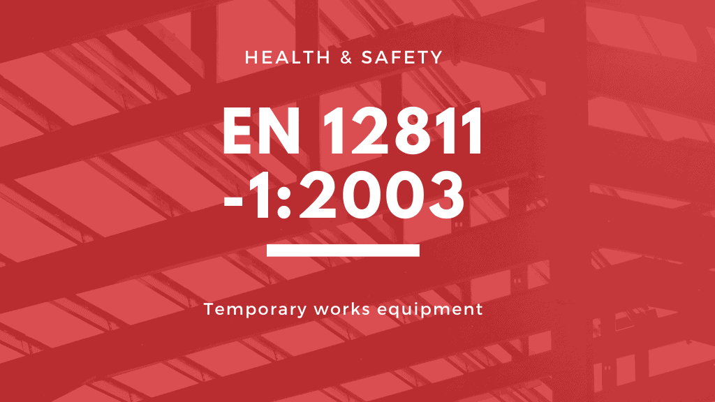
5.5 Side protection
5.5.1 General
Working and access areas shall be safeguarded by side protection consisting of at least a principal guardrail,
intermediate side protection, and a toeboard. See Figure 3. The toeboard may be dispensed with on stairways.
Side protection shall be secured against unintended removal.
For structural design requirements, see clause 6.
NOTE 1 The side protection should not be provided by cladding on its own.
NOTE 2 For special cases e.g. use of working scaffolds in vertical formwork there may be a need of inclined side protection,
which is outside the field of application of this standard.
The principal guardrail shall be fixed so that its top surface is 1 m or more above the adjacent level of the working
area everywhere (absolute minimum height 950 mm).
5.5.3 Intermediate side protection
Intermediate side protection shall be fixed between the principal guardrail and the toeboard.
Intermediate side protection may consist of:
one or more intermediate guardrails, or
a frame, or
a frame of which the principal guardrail forms the top edge, or
a fencing structure
Openings in the side protection shall be so dimensioned that a sphere with a diameter of 470 mm will not pass
through them.
5.5.4 Toeboard
A toeboard shall be fixed so that its top edge is at least 150 mm above the adjacent level of the working area.
Holes and slots in a toeboard shall, except for handling holes be no larger than 25 mm in one direction.
5.5.5 Fencing structures
The area of each hole or slot in fencing structures shall not exceed 100 cm2
. In addition, the horizontal dimension
of each hole or horizontal slot shall not exceed 50 mm.
5.5.6 Location of the components of the side protection
The horizontal distance between the outer face of the toeboard and the inner face of the guardrail and all the
components of the intermediate side protection shall not exceed 80 mm.
5.6 Cladding
Where cladding of the working scaffold is required, this standard assumes that the scaffold will be clad with either
netting or sheeting.
5.7 Base plates and base jacks
5.7.1 General
The strength and rigidity of the base plates and base jacks shall be sufficient to ensure that they can transmit the
maximum design load from the working scaffold to the foundations. The area of the endplate shall be a minimum
of 150 cm2
. The minimum width shall be 120 mm.
5.7.2 Baseplates
Base plates made of steel shall conform to EN 74.
5.7.3 Base jacks
Base jacks shall be provided with a centrally positioned adjusting spindle of such dimensions that, in the unloaded
condition, the greatest inclination of the axis of the shaft from the axis of the standard does not exceed 2,5 %. The
minimum overlap length at any position of adjustment shall be 25 % of the total length of the shaft, or 150 mm
whichever is greater. The thickness of the endplate shall be at least 6 mm. Shaped endplates shall have at least
the same rigidity.
5.7.4 Joints between standards with hollow sections
The overlap length in joints between standards shall be at least 150 mm. It may be reduced to a minimum of 100
mm if a locking device is provided.
5.8 Access between levels
5.8.1 General
Safe and ergonomic means of access shall be provided.
The scaffold system shall include provision for access between the different levels. This shall be by inclined ladders
or stairs. It shall be within the platform, within a widening of the working scaffold at one bay, or in a tower
immediately adjacent.
Ladders in accordance with EN 131-1 and EN 131-2 may be assumed to satisfy the requirements for access in this
standard.
The stairways and ladders shall be secured against unintentional loosening and shall have a slip-resistant surface.
NOTE 1 When extensive work is carried out, stairways should be provided for access.
NOTE 2 For taller scaffolds consideration should be given to the use of a passenger hoist.
5.8.2 Stairways
To cater to different requirements for stairways this European Standard specifies two classes of stairway
dimensions. The dimensions of stair flights shall be in accordance with Figure 4 and the following:
The combination of values for the rise, u, and the going, g, shall be in accordance with expression (1):
540 ≤ 2u + g ≤ 660 in mm (1)

The clear dimensions of access opening in a platform shall be at least 0,45 m wide, measured across the width
of the platform, and 0,60 m long. Should it not be possible to close the opening by means of a permanently
attached trapdoor, it shall be possible to install a protective railing. The trapdoor shall be fastenable in the closed
position.
6 Requirements for structural design
6.1 Basic requirements
6.1.1 General
Each working scaffold shall be designed, constructed, and maintained to ensure that it does not collapse or move
unintentionally and so that it can be used safely. This applies at all stages, including erection, modification, and until
fully dismantled.
The scaffold components shall be designed so they can be safely transported, erected, used, maintained,
dismantled and stored.
6.1.2 External support
A working scaffold shall have support or foundation capable of resisting the design loads and limiting movement.
Lateral stability of the scaffold structure as a whole and locally shall be verified when subjected to the different
design forces, for example from the wind.
NOTE 1 Lateral stability can be provided by tie members to the adjacent building or structure. Alternatively other methods,
such as guy ropes, kentledge or anchors may be used.
NOTE 2 It may be necessary to remove individual ties temporarily in order to carry out work on the permanent structure. In
such a case removal of the ties should be taken into consideration in the design and a method statement prepared to specify
the sequence for removal and replacement of ties.
6.1.3 Load classes
To cater to different working conditions, this European Standard specifies six load classes and seven width classes
of working areas. The service loads are set out in Table 3.
The load class for working areas shall correspond to the nature of work.
NOTE In exceptional cases, where it is impractical to adopt one of the load classes or the activity is more onerous, different
parameters may be adopted and specified after analysis of the use to which the working scaffold will be put. Consideration
should be given to the actual activities to be undertaken. Some examples of items to be considered are:
a) The weight of all equipment and materials stored on the working area,
b) Dynamic effects from the material placed on the working area by powered plant and
c) Load from manually operated plant such as wheelbarrows.
Storage of materials on working scaffolds of load class 1 is not covered by the service loads specified in Table 3.

6.2.1 General
The values specified in 6.2 shall be treated as characteristic values of the actions (loads).
There are three main types of loading which need to be considered:
a) Permanent loads; these shall include the self-weight of the scaffold structure, including all components, such
as platforms, fences, fans, and other protective structures and any ancillary structures such as hoist towers.
b) Variable loads; these shall include service loads (loading on the working area, loads on the side protection)
and wind loads and, if appropriate, snow and ice loads (see 6.2.6).
c) Accidental loads; the only accidental load specified in this European Standard is the loading according to
6.2.5.1.
Loadings given in 6.2.2 and 6.2.5 do not cover actions from people jumping or falling down from a height onto the
platform or onto the side protection.
6.2.2 Loading on the working area
6.2.2.1 General
The service loads shall be as specified in Table 3. Each working area shall be capable of supporting the various
loadings, q1, F1 and F2, separately but not cumulatively. Only the uniformly distributed load, q1, has to be carried
down to the support of the scaffold structure, for birdcage scaffolds the partial area loads also, see Figure 5d.
For the purposes of structural design, service loads on the working area shall be applied over an area determined
as follows:
Where there are contiguous platforms along or across the working scaffold, the dividing edge shall be taken as a
centreline between the supporting standards.
At any outer edge the dimension, w, shall be taken to the actual edge or, where there is a toeboard, as it is
defined in 5.2. See figure 2.
For working scaffolds of load class 1, all platform units shall be capable of supporting Class 2 service load, but this
shall not apply to the scaffold structure in its entirety
6.2.2.2 Uniformly distributed service load
Each working area shall be capable of supporting the uniformly distributed load, q1, specified in Table 3.
6.2.2.3 Concentrated load
Each platform unit shall be capable of supporting the load, F1, specified in Table 3, uniformly distributed over an
area of 500 mm x 500 mm and, but not simultaneously, the load, F2, specified in Table 3, uniformly distributed over
an area of 200 mm x 200 mm.
The load path shall be capable of transferring the forces caused by the loads to the standards. The position of each
the load shall be chosen to give the most unfavorable effect.
When a platform unit is less than 500 mm wide, the load, F1, according to Table 3, may be reduced for this unit in
proportion to its width, except that in no case, shall the loading be reduced to less than 1,5 kN.
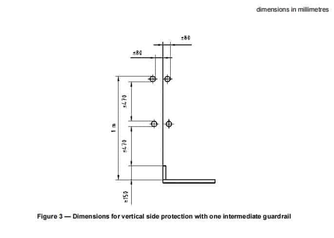
6.2.2.4 Partial area load
Each platform of load classes 4, 5, and 6 shall be capable of supporting a uniformly distributed partial area loading, q2,
which is a loading greater than the uniformly distributed service load. The partial area is obtained by multiplying the
area of the bay, A, by the partial area factor ap. Values of q2 and ap are given in Table 3. Area A is calculated
from the length, l, and the width w, of each platform, see Figure 5.
The load path shall be capable of transferring the forces caused by the loads to the standards.
Where there are more than two standards in both directions, as in a birdcage, the partial area loads of four
contiguous bays shall be considered for the verification of the respective supporting standard, see Figure 5d).
The dimensions and position of the partial area shall be chosen to give the most unfavorable effect. Some
examples are shown in Figure 5.

structural components
6.2.2.5 Cantilevered portions of a working area
All cantilevered portions of a working area shall be capable of supporting the service load specified for the main
working area (see 6.2.2.2, 6.2.2.3 and 6.2.2.4).
If the levels of the cantilevered portions and the main working area differ by 250 mm or more, they may
be of different load classes, according to Table 3.
6.2.2.6 Birdcage scaffolds
The load on the supporting components of a birdcage scaffold shall be calculated by assuming that the uniformly
distributed load q1 specified in Table 3 acts on an area of maximum of 6,0 m2
in combination with a load of 0,75 kN/m2
over the remaining area.
6.2.3 Horizontal working load allowance
In the absence of wind, the working scaffold shall be capable of supporting a notional horizontal working load,
representing operations during use, acting at all of the levels where the working area is loaded.
For each bay considered the notional horizontal load shall be not less than 2,5 % of the total of the uniformly
distributed load, q1, specified in Table 3, on that bay, or 0,3 kN, whichever is the greater. The load shall be assumed
to act at the level of the working area and shall be applied separately parallel and perpendicular to the bay.
6.2.4 Access routes
Except for class 1 working scaffolds, horizontal access routes shall be capable of supporting at least the class 2
service loading, specified in Table 3.
When a part of an access route is to be used for working, it shall be capable of supporting the relevant service load
prescribed in Table 3. Normally a landing, which is at the same level as a working area but outside of it, need not be
capable of supporting the same load.
For stairways built for access to a working scaffold, each tread and landing shall be designed to support the more
unfavorable of:
either
a) a single load of 1,5 kN in the most unfavorable position, assumed to be uniformly distributed over an area of
200 mm x 200 mm or over the actual width if it is less than 200 mm,
or
b) an uniformly distributed load of 1,0 kN/m2.
The structure of the stairways shall be capable of supporting a uniformly distributed load of 1,0 kN/m2
on all treads
and landings within a height of 10 m.
6.2.5 Loads on the side protection
6.2.5.1 Downward loading
Any principal guardrail and intermediate guardrail, regardless of its method of support, shall be capable of resisting
a point load of 1,25 kN. This also applies to any other side protection component, which replaces principal
guardrails and intermediate guardrails such as a fencing structure, which has gaps in excess of 50 mm width.
This load shall be considered as an accidental load and shall be applied in the most unfavorable position in a
downward direction within a sector of ± 10o from the vertical.
6.2.5.2 Horizontal loading
All components of the side protection, except toeboards, shall be designed to resist a horizontal point load of 0,3 kN
in each case in the most unfavorable position. This load may be distributed over an area of a maximum of 300 mm x
300 mm, for example, when applied to the grid of a fencing structure. For toeboards, the horizontal point load is 0,15
kN.
6.2.5.3 Upward loading
To check the fixing of all side protection components, except the toeboard, a point load of 0,3 kN shall be applied
vertically upwards in the worst position.
6.2.6 Snow and ice loads
An allowance for snow and ice loading on a working scaffold may be required by national regulations.
6.2.7 Wind loads
6.2.7.1 General
Wind loads shall be calculated by assuming that there is a velocity pressure on a reference area of the working
scaffold, which is, in general, the projected area in the wind direction. The resultant wind force, F, in kN, is obtained
from equation (2):
= ∑i F cs x (cf,i x Ai x qi) (2)
where
F is the resultant wind force;
cf, i is the aerodynamic force coefficient for the scaffold component I (see 6.2.7.2);
Ai is the reference area of the scaffold component i;
qi is the velocity pressure acting on the scaffold component I;
cs is the site coefficient (see 6.2.7.3).
Shielding effects shall not be taken into account.
The following subclauses 6.2.7.2 and 6.2.7.3 relate to unclad working scaffolds only. For wind loads on clad
working scaffolds see Annex A.
6.2.7.2 Aerodynamic force coefficient, cf
Aerodynamic force coefficients, cf, appropriate for some cross-sections of scaffold components given in ENV 1991-
2-4 shall be used when calculating the wind force on a working scaffold.
For other cross-sections, the aerodynamic force coefficients may be taken from national standards or
maybe determined by wind tunnel testing.
The value of the aerodynamic force coefficient, cf, shall be taken as 1,3 for all projected areas including platforms,
toeboards and the nominal area defined in 6.2.7.4.1 or 6.2.7.4.2 respectively.
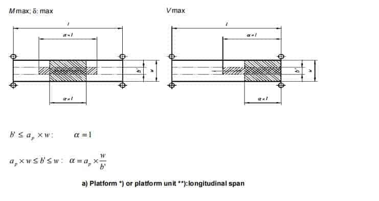
6.2.7.3 Site coefficient, cs
6.2.7.3.1
The site coefficient, cs takes into account the location of the working scaffold in relation to a building, for example in
front of a façade. The site coefficient cs according to 6.2.7.3.2 and 6.2.7.3.3 applies to a facade with openings,
which are distributed regularly over its area.
6.2.7.3.2
For wind forces normal to the façade, the value of cs⊥ is to be taken from Figure 6. It depends on the solidity ratio,
ϕB, which is given by equation (3):
ϕ B=AB,n /AB,g
where
AB n is the net area of the façade (with the openings deducted);
AB, g is the gross area of the facade.
6.2.7.3.3
For wind forces parallel to the façade, the value of cs shall be taken as 1,0.
6.2.7.4 Velocity pressure
6.2.7.4.1 Maximum wind loading
The maximum wind loading for the region shall take into account the type and location of the site.
When the European Standard for wind loads is available it shall be used. Pending its availability, data shall be taken from national standards. A statistical factor considering the period of time from the erection to the dismantling of the working scaffold may be taken into account. This factor shall be not less than 0,7 and shall be applied to the
wind velocity pressure for a 50-year return period.
NOTE For the purposes of the structural design of façade scaffolds made of prefabricated components, design velocity pressures are given in EN 12810-1. These pressures will normally not be exceeded in most of Europe. The actual wind conditions should be checked.
To make allowance for equipment or materials which are on the working area, a nominal reference area shall be assumed at its level over its full length. This area shall be 200 mm high measured from the level of the working area and includes the height of the toeboard. The loads resulting from the wind pressure on this area shall be assumed to act at the level of the working area
6.2.7.4.2 Working wind load
A uniformly distributed velocity pressure of 0,2 kN/m2
shall be taken into account. To make allowance for
equipment or materials being on the working area, a nominal reference area as defined in 6.2.7.4.1, but 400 mm
high, shall be used in calculating working wind loads.
6.2.8 Dynamic loading
The following figures may be taken as equivalent static loads to represent the excess loading caused by dynamic
effects in-service conditions.
a) The dynamic effect of the load from an individual item, except people, moving vertically by powered means
shall be represented by a 20 % increase in the weight of the item.
b) The dynamic effect of a load from an individual item moving horizontally, except people, shall be represented
by an equivalent static force of 10 % of the weight of the item, acting in any of the practical possible horizontal
directions.
NOTE For dynamic loading resulting from people falling down from a height on platforms of facade scaffold made of
prefabricated components see EN 12810-1.
6.2.9 Load combinations
6.2.9.1 General
Each working scaffold structure shall be capable of resisting the worst combinations of loads to which it is likely to
be subjected. The conditions on-site shall be established and load combinations determined accordingly.
For façade scaffolds, load combinations are given in 6.2.9.2. These load combinations may also be appropriate for
types of working scaffold different from facade scaffolds.
6.2.9.2 Facade scaffolds
The combinations a) and b) shall be used for the structural design of facade scaffolds unless reliable information on
the manner of use of the scaffold is available.
In each individual case, the service condition and the out-of-service condition shall be considered.
a) The service condition
1) The self-weight of the scaffold, see 6.2.1.
2) Uniformly distributed service load appropriate to the class of the working scaffold specified in Table 3,
column 2, acting on the working area of the most unfavorable decked level.
3) 50% of the load specified in a)2) shall be taken to act on the working area at the next level above or
below if a working scaffold has more than one decked level.
4) Working wind load specified in 6.2.7.4.2 or horizontal working load allowance specified in 6.2.3.
b) The out of service condition
1) The self-weight of the scaffold, see 6.2.1.
2) A percentage of the uniformly distributed load, specified in Table 3, column 2, acting on the most
unfavorable decked level. The value depends on the class:
class 1: 0 %; (no service load on the working area);
classes 2 and 3: 25%; (representing some stored materials on the working area);
classes 4, 5, and 6: 50%; (representing some stored materials on the working area)
3) The maximum wind load specified in 6.2.7.4.1.
In cases a) 2) and b) 2), the load shall be taken as zero if its consideration leads to more favorable results; for
example in the case of overturning.
6.3 Deflections
6.3.1 Elastic deflection of platform units
When subjected to the concentrated loads specified in Table 3, columns 3 and 4 the elastic deflection of any
platform unit shall not exceed 1/100 of its span.
Furthermore, when the appropriate concentrated load is applied, the maximum deflection difference between
adjacent loaded and unloaded platform units shall not exceed 25 mm.
6.3.2 Elastic deflection of the side protection
Each principal or intermediate guardrail and toeboard, regardless of its span, shall not have an elastic deflection
greater than 35 mm, when subjected to the horizontal load specified in 6.2.5.2.
This is measured with reference to the supports at the points where the component is fixed.
6.3.3 Deflection of fencing structures
When subjected to the horizontal load specified in 6.2.5.2, the grid of a fencing structure shall not deflect more than
100 mm with reference to its supports.
When a fencing structure is combined with a guardrail, the requirements for a guardrail shall be satisfied
separately.
7 Product manual
For prefabricated components and systems, a manual shall be made available to enable the product to be used
safely. For façade scaffolds made of prefabricated components see EN 12810-1.
8 Instruction manual
For each type of prefabricated scaffold system, the relevant instruction manual should be available on-site, and shall
include at least the following:
a) procedure during erection and dismantling the working scaffold, describing the correct sequence of working
steps. This instruction procedure shall include drawings and text;
b) scheme and its details;
NOTE These requirements may be met by standard data, specially prepared information, or a combination of the two.
c) loads imposed by the working scaffold on its foundation and on the building structure;
d) information about the class of working scaffold, the number of working areas which may be loaded and the
permitted height for different conditions;
e) detailed information about fixing and dismantling of the components;
f) information about tying in working scaffolds.
g) any other limitations.
For requirements regarding an instruction manual for façade scaffolds made of prefabricated components see
clause 9 of EN 12810-1:2003.
9 Work on site
9.1 Basic assumption
The design will assume that the erection, use, modification, and dismantling will be in accordance with the prepared
scheme (drawings, specification, and other instructions) and that maintenance of the scaffold structure including its
tying and foundations will be provided and will be in a condition to meet the requirements of the design. (See 1.3 of
ENV 1991-1:1994 for more details).
9.2 Actions on site
The ability of the foundations to support the load calculated in the design shall be verified. Where lateral support is
to be provided by the structure served both the structural adequacy of that structure and the attachment of the
anchorages shall be verified.
NOTE Verification should be carried out by a person who has the competence to do so and who is normally either
responsible for the design or the erection.
10 Structural design
10.1 Basic design principles
10.1.1 Introduction
Working scaffolds shall be designed for stability and serviceability. This includes load-bearing capacity and
positional stability against sliding sideways, uplift, and overturning. Unless otherwise stated in this clause, the
European Standards for structural engineering shall be applied.
Concepts related to the limit state method.
Global or detail testing may be carried out to supplement calculation. The testing shall be carried out in accordance
with EN 12811-3.
10.1.2 Structural design of components
10.1.2.1 Steel
The structural design shall be in accordance with ENV 1993-1-1.
10.1.2.2 Aluminium
The structural design shall be in accordance with ENV 1999-1-1.
10.1.2.3 Timber
The structural design shall be in accordance with ENV 1995-1-1.
10.1.2.4 Other materials
The structural design shall be in accordance with appropriate European Standards. If they do not exist, they may be in
accordance with ISO Standards.
10.1.3 Limit states
The limit states are classified into:
- ultimate limit states;
- serviceability limit states.
At the ultimate limit state the design value for the effect of actions, that is the design value of an internal force or
moment, Ed, shall not exceed the design value of the corresponding resistance, Rd, in accordance with the
expression (4)
Ed ≤ Rd (4)
The design value, Ed, for the effect of actions is calculated from the characteristic values of the actions specified in
6.2 by multiplying each by the corresponding partial safety factor, γF.
The design value of the resistances, Rd is calculated from the characteristic resistance values specified in 10.2.4 by
dividing by a partial safety factor, γM.
At serviceability limit state the design value of the effect of actions specified in the serviceability criterion shall not
exceed the limiting design value of the corresponding serviceability criterion, Cd, see expression (5). This applies,
for example, to deflections.
Ed ≤ Cd (5)
10.2 Structural analysis
10.2.1 Choice of model
The models adopted shall be sufficiently accurate to predict the structural behavior level taking into account the
imperfections gave in 10.2.2.
The analysis carried out by checking separate planar systems shall consider the interaction.
The connection between the ties and the façade shall be modeled so that the ties are free to rotate about axes in
the plane of the façade and shall not be assumed to transmit vertical forces.
10.2.2 Imperfections
10.2.2.1 General
The effects of practical imperfections, including residual stresses and geometrical imperfections, such as out of
vertical, out of straight and unavoidable minor eccentricities shall be taken into account by a suitable equivalent
geometric imperfections.
The method of application shall be in accordance with the respective specifications of the relevant design
standards, for example, for steel ENV 1993-1-1and for aluminum ENV 1999-1-1. Deviating from these
specifications, the assumptions concerning imperfections in global frame analysis shall comply with 10.2.2.2.
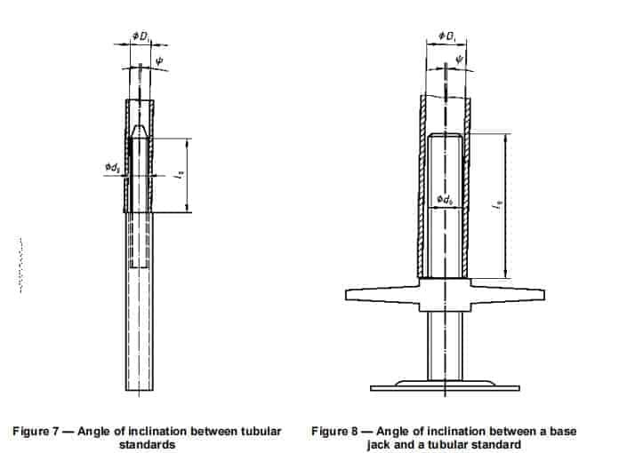
10.2.2.2 Inclinations between vertical components
Frame imperfections by angular deviations at the joints between vertical components shall be taken into account.
For a joint in a tubular standard, the angle of inclination, Ψ, either between a pair of tubular components connected
by a spigot permanently fixed to one of the components (see Figure. 7) or between a base jack and a tubular
component (see Figure. 8), maybe calculated from equation (6):
tanΨ= (D i− d0)/I0
(6)
tan Ψ may not be less than 0,01
where Di is the nominal inner diameter of the tubular standard; d0 is the nominal outer diameter of the spigot or base jack; l0 is the nominal overlap length. Ψ see Figure 7 and Figure 8 respectively.
When there are a number, n, of standards with such joints side by side and when planned pre-deflections are excluded, a reduced value for Ψ, represented by ψn, may be calculated from equation (7):
This applies to working scaffolds where the length of the ledgers are not predetermined by connecting devices, for
example for tubes and coupler scaffolds.
In the case of a façade scaffold made of prefabricated components, the value of tan ψ for a closed frame in its
the plane may be taken as 0,01 if the vertical overlap length is at least 150 mm; and as 0,015, if the overlap length is
less, see 5.7.4.
Requirements of 10.2.3.1 also apply
10.2.3 Rigidity assumptions
1.1.1.1 Joints between tubular members
The joints between tubular members may be assumed to be rigid connections if the spigot is permanently fixed to
one standard and if:
- the overlap length of the spigot is at least 150 mm or, in the case of locking device, at least 100 mm; and
- the play between the nominal inner diameter of the tube and the nominal outer diameter of the spigot is not
greater than 4 mm.
This assumption applies only to tubular members with external diameters not exceeding 60 mm.
Where neither of these requirements is met, for example, if spigots according to EN 74 are used, the joints shall
be modeled as ideal hinges. In this case frame imperfections, i.e. the angle between the linked standards (see
10.2.2.2) may be omitted. Alternatively, a detailed check on the spigot and the standard may be done (see 10.3.3.
3).
10.2.3.2 Base jacks
The stiffness of base jacks made of steel and with trapezoidal or round-shaped rolled threads shall, in the absence
of any other data, be determined using, the formula in Annex B.
The point of support of the base jacks with fixed endplates may be modeled by a bi-linear spring in accordance
with the moment-rotation characteristic shown in Figure 9.
The value for the ultimate bending resistance, Mu, shall be in accordance with the following equation (8):
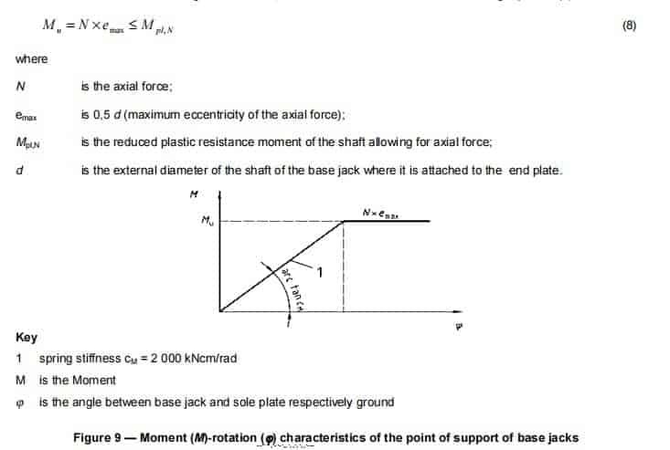
zone shall be taken into account.
10.2.3.3 Baseplates
The point of support of base plates complying with EN 74 shall be assumed as an ideal hinge.
10.2.3.4 Connecting devices
10.2.3.4.1 General
The realistic load-deformation behavior of the connecting devices is to be incorporated in the model for the
analysis. Alternatively, joints may be modeled by assumptions that are on the safe side.
NOTE ENV 1993-1-1 and EN 12811-3 give some information on semi-rigid connections.
For the determination of the relevant parameters for semi-rigid connecting devices in facade scaffold made of
prefabricated components, see EN 12810-2.
Where the connections to standards are made by prefabricated joints, for example in a modular system, the design
moment-rotation characteristic of ledger-to-standard or transom-to-standard connections shall be determined.
10.2.3.4.2 Right angle couplers (prEN 74-1, class B )
The cruciform stiffness cϕ, that is the relationship between the cruciform bending moment (MB) and angle of
cruciform rotation ϕ, of class B right-angle couplers attached to steel or aluminum tubes, is shown in Figure C.1.
Design values to be used in Figure C.1 are given in Table C.2. This relationship corresponds to the mean value of
the cruciform stiffness, which may be applied to the evaluation of forces and moments of the overall scaffold
system.
NOTE 1 Figure C.1 and the values in Table C.2 also allow the use of class B couplers complying with EN 74:1988.
In some cases, the rotational resistance of right-angle couplers will be used, for example in the connection between
standard and tie members. The rotational stiffness cϑ, that is the relationship between rotational moment, MT, and
angle of rotation ϑ, of class B right-angle couplers attached to steel or aluminum tubes, is shown in Figure C.2.
This only applies to couplers, which are secured by screwed means. Design values to be used in Figure C.2 are
given in Table C.3. Wedge couplers and class A couplers may not be assumed to transmit rotational forces.
In special cases, where deformations have a major effect on the stability of a scaffold structure, for example in freestanding working scaffolds, the axial deformations of the coupler joints shall be taken into account by a longitudinal
spring with an appropriate stiffness.
NOTE 2 The values of Table C.1 also allow the use of class B couplers complying with EN 74:1988
10.2.4 Resistances
10.2.4.1 General
The characteristic values of the resistances shall be calculated using the characteristic values of the mechanical
properties (for example the yield strength fy, k) which are given in prEN 12811-2 or maybe taken from relevant
standards.
For steel or aluminum members the resistances shall be determined in accordance with 5.4 of ENV 1993-1-1:1992
or 5.3 of ENV 1999-1-1:1998 respectively.
10.2.4.2 Connecting devices
To establish the characteristic values of resistances for
a) connections covered by the scope of structural engineering regulations: see relevant design standards;
b) semi-rigid connection devices for facade scaffold made of prefabricated components: see EN 12810-2 and EN
12811-3;
c) couplers complying with prEN 74-1: See Annex C;
NOTE The values of Table C.1 also allow the use of class B couplers complying with EN 74:1988
d) other connection devices, which do not comply with a standard: tests shall be carried out.
See e.g. EN 12810-2.
10.2.4.3 Base jacks
The characteristic values of the resistances of base jacks made of steel with trapezoidal or round-shaped rolled
threads shall be calculated in accordance with Annex B.
The connection between the collar-nut providing adjustment and the shaft shall be in accordance with a relevant
thread standard. Otherwise, its load-bearing capacity shall be verified by testing.
The verification of the load-bearing capacity of the jack shall be carried out as part of the calculation of the whole
working scaffold.
10.3 Verification
10.3.1 General
For the determination of internal forces and moments, elastic methods shall be used (exception see 10.2.3.2). For
For example for steel sees ENV 1993-1-1:1992, clause 5.2.1.3.
The influence of the deflections on the internal forces and moments shall be taken into account; the equilibrium of
the displaced system shall be calculated by the use of a second-order analysis or by the use of a first-order
analysis with amplification factors.
Transfer paths for the loads specified in Table 3 to the vertical members shall be verified.
For façade scaffolds made of prefabricated components systems, EN 12810-1 and EN 12810-2 apply.
10.3.2 Partial safety factors
1.1.1.1 Partial safety factors for actions, γF
Except where stated otherwise, the partial safety factors, γF, shall be taken as follows:
Ultimate limit state
- γF = 1,5 for all permanent and variable loads
- γF = 1,0 for accidental loads
Serviceability limit state - γF = 1,0
10.3.2.2 Partial safety factors for resistance γM
For the calculation of the design values of the resistances of steel or aluminum components the partial safety
factor, γM shall be taken as 1,1. For components of other materials the partial safety factor, γM, is to be taken from
relevant standards.
For the serviceability limit state, γM shall be taken as 1,0
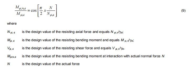
10.3.3 Ultimate limit state
10.3.3.1 General
At the ultimate limit state, it has to be verified that the design values of the effects of actions do not exceed the design values of the corresponding resistances. 10.3.3.2 Tubular members For the combination of internal forces, the interaction equation (9) may be used, provided that the design value of the actual shear force V ≤ 1/3 Vpl, d
10.3.3.3 Joints between tubular members
When the requirements of a rigid connection between tubular members according to 10.2.3.1 are met, the spigot
only needs to be verified for the design bending moment at the joint.
When the overlap is less than 150 mm and the joint is not treated as a hinge, see 10.2.3.1, the detailed structural
design check shall include the bending stresses, shear stresses, and local bearing stresses.
10.3.3.4 Side protection
Components of the side protection shall withstand the accidental load specified in 6.2.5.1 without failing or
disconnecting. A displacement from the original line of more than 300 mm at any point is to be taken as a failure.
Where necessary the displacement may be calculated by assuming a plastic hinge, which transfers the plastic
bending resistance of the component.
10.3.3.5 Couplers
It has to be verified that the design values of the forces acting on the couplers do not exceed the corresponding
design values of the resistances according to annex C taking into account the partial safety factor in accordance
with 10.3.2.2. If couplers are subjected to a combination of actions, in addition, it has to be verified that the
expression (10) and or (11) is met.
Right angle couplers:

It shall be verified that the deflection requirements specified in 6.3 are met.
10.4 Positional stability
Freestanding working scaffolds as a whole shall be checked against sliding sideways, uplift and overturning.
Working scaffolds shall be verified for local sliding.
Verification methods are given in prEN 12812.