Foreword
This document EN 13374:2004 has been prepared by Technical Committee CEN/TC 53 “Temporary works
equipment”, the secretariat of which is held by DIN.
This European Standard shall be given the status of a national standard, either by the publication of an identical
text or by endorsement, at the latest by December 2004, and conflicting national standards shall be withdrawn
at the latest by December 2004.
The standard is intended to cover equipment for temporary edge protection appropriate for use throughout Europe.
Annex A is normative. Annex B is informative.
According to the CEN/CENELEC Internal Regulations, the national standards organizations of the following countries are bound to implement this European Standard: Austria, Belgium, Czech Republic, Cyprus, Denmark, Estonia, Finland, France, Germany, Greece, Hungary, Iceland, Ireland, Italy, Latvia, Lithuania, Luxembourg, Malta, Netherlands, Norway, Poland, Portugal, Slovakia, Slovenia, Spain, Sweden, Switzerland, and the United Kingdom
Introduction
Temporary edge protection systems are used in construction work, primarily to prevent persons and objects from falling to a lower level from roofs, edges, stairs, and other areas where protection is required. In several European countries temporary edge protection, or other types of fall protection devices, are required when the fall height is more than 2 m. In contrast to being secured by a lanyard, greater mobility in the working area is provided when edge protection is in place. The temporary edge protection can in some situations also act as a handrail for people to hold onto when working or walking close to an edge. While this standard also includes requirements to protect people from falling objects, e.g. by the provision of toeboards, there could be circumstances where this is insufficient and additional measures, which are beyond the scope of this document, will need to be taken. Classes specified in this standard are intended to cater to the varied requirements appropriate for different uses. It is important that the structure to which temporary edge protection is attached can support the forces that the system is designed for.
1. Scope
This European Standard specifies the requirements and test methods for temporary edge protection systems for use during the construction or maintenance of buildings and other structures.
This standard applies to edge protection systems for flat and inclined surfaces and specifies the requirements for three classes of temporary edge protection.
For edge protection systems with an arrest function (e.g. falling or sliding down a sloping roof) this standard specifies requirements for energy absorption.
This standard includes edge protection systems, some of which are fixed to the structure, and others, which rely on gravity and friction on flat surfaces.
This standard does not provide requirements for edge protection systems intended for:
Protection against impact from vehicles or from other mobile equipment,
Protection from sliding down of bulk loose materials, snow, etc.,
Protection of the general public from falling.
This standard does not apply to side protection systems on scaffolds.
2. Normative references
This European Standard incorporates by dated or undated reference, provisions from other publications.
These normative references are cited at the appropriate places in the text and the publications are listed hereafter. For dated references, subsequent amendments to or revisions of any of these publications apply to this European Standard only when incorporated in it by amendment or revision. For undated references, the latest edition of the publication referred to applies (including amendments).
prEN 74-1, Couplers, spigot pins, and baseplates for use in falsework and scaffolds — Part 1: Couplers for tubes — Requirements and test methods.
EN 338, Structural timber — Strength classes.
EN 364:1992, Personal protective equipment against falls from a height — Test methods.
EN 596, Timber structures – Test methods — Soft body impact test of timber-framed walls.
EN 1263-1, Safety nets — Part 1: Safety requirements, test methods.
EN 12811-1, Temporary works equipment — Part 1: Scaffolds — Performance requirements and general design.
EN 12811-2, Temporary works equipment — Part 2: Information on materials.
EN 12811-3:2002, Temporary works equipment — Part 3: Load testing.
ENV 1990, Eurocode 1 — Basis of structural design.
ENV 1993-1-1, Eurocode 3 — Design of steel structures — Part 1-1: General rules and rules for buildings.
ENV 1995-1-1, Eurocode 5 — Design of timber structures — Part 1-1: General rules and rules for buildings.
ENV 1999-1-1, Eurocode 9 — Design of aluminium structures — Part 1-1: General rules — General rules and
rules for buildings.
3. Terms and definitions
For the purposes of this European Standard, the following definitions apply.
3.1 edge protection system
set of components intended to protect people from falling to a lower level and to retain materials see Figure 1
3.2 principal guardrail
rail or continuous element forming the top of the edge protection system
3.3 intermediate guardrail
guardrail positioned between the principal guardrail and the working surface
3.4 intermediate protection
protection barrier formed (e.g. as a fencing structure or a safety net) between the principal guardrail and the
working surface, see Figure 2.
3.5 toeboard
upstand provided specifically to prevent materials or persons from falling or sliding off a surface
3.6 post
principal vertical support of the edge protection system to which the guardrails and toeboards are attached
3.7 falling height, HF
the vertical distance between the point on which a person stands and the lowest point on the protection intended
to arrest any fall
NOTE See Figure 3.
3.8 height of the edge protection
distance between the uppermost point of the principal guardrail and the working surface measured perpendicular to the working surface
3.9 working surface
the surface on which persons stand, walk or work.
3.10 counterweight
component intended to restrain the edge protection system from sliding acting by friction or overturning
NOTE Figure 1 illustrates some of the various types of edge protection.
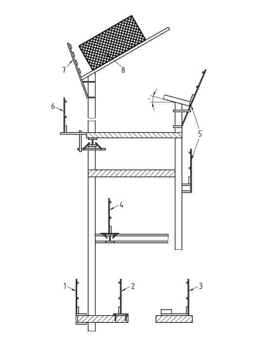
Key
1 Slab edge clamp system 2 Fixed to floor type system 3 Counterweighted system 4 Beam top flange clamp system 5 Column clamp system – floors and flat roofs 6 Beam bottom flange clamp 7 Column clamp system – sloping roof 8 Fencing system
Figure 1 — Diagrammatic examples of different types of temporary edge protection

4. Classification of edge protection systems
4.1 Class A
Class A protection provides resistance to static loads only, based on the requirements to:
support a person leaning on the protection or provide a handhold when walking beside it, and
arrest a person who is walking or falling towards the protection.
4.2 Class B
Class B protection provides resistance to static loads and low dynamic forces only, based on the requirements
to:
support a person leaning on the protection or provide a handhold when walking beside it; and
arrest a person who is walking or falling towards the protection;
arrest the fall of a person sliding down a sloping surface.
4.3 Class C
Class C protection provides resistance to high dynamic forces based on the requirements to arrest the fall of a person sliding down a steeply sloping surface.
arrest the fall of a person sliding down a steeply sloping surface.
NOTE More guidance about the use of classes is given in annex B.
5. Requirements
5.1 General
5.1.1 Basic requirements
An edge protection system shall comprise at least a principal guardrail and an intermediate guardrail or intermediate protection, and it shall be possible to attach a toeboard.
NOTE It is important that components have a surface and be so located that injury to a person from puncturing or
lacerating the skin is minimized.
5.1.2 Nets
Safety nets used as side protection shall be system U in accordance with EN 1263-1.
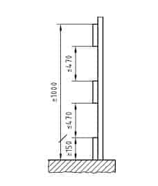
5.1.3 Principal guardrail
The distance between the uppermost part of the edge protection and the working surface shall be at least
1,0 m measured perpendicular to the working surface, see Figures 4 .
5.1.4 Toeboard
The upper edge of the toeboard shall be at least 150 mm above the working surface, see Figures 4 and 5.
The toeboard should be designed to avoid gaps between it and the working surface on normally a flat working
surface.
If there are gaps, a sphere with a diameter of 20 mm shall not pass through them.
NOTE For other situations for example where the working surface is not flat, any gaps should be maintained as close
as practicable to this figure.
5.2 Additional requirements for individual classes
5.2.1 Edge protection system class A
The inclination of edge protection system class A shall not deviate from the vertical by more than 15°.
If an intermediate guardrail is provided, any gap shall be so dimensioned that a sphere of 470 mm diameter
will not pass through the protection. If there is no intermediate guardrail or if it is not continuous, the edge protection system shall be so dimensioned that a sphere with a diameter of 250 mm will not pass through it.
If it is not possible to verify the load requirements by calculation (see 6.1.1), the static load tests specified in
7.4.2 and 7.4.3 shall be carried out and for class A edge protection. In this case, to comply with this standard:
a) On the completion of the test specified in 7.4.2 the adjusted elastic deflection δ shall not exceed the
value specified in 6.3.5;
b) On completion of the test specified in 7.4.3, the adjusted strength RU shall be not less than 1.2 times
the maximum test load; and
c) The residual deflection, δ3, shall not exceed 10 % of the deflection at maximum load, δmax.
NOTE δ, δ3, δmax, and RU are defined in 7.4.2 and 7.4.3.
5.2.2 Edge protection system class B
The inclination of edge protection system class B shall not deviate from the vertical line AC by more than 15°,
see Figure 5.
Any gap in a class B side protection shall be so dimensioned that a sphere of 250 mm diameter will not pass
through the protection.
If it is not possible to verify the load requirements by calculation (see 6.1.1), the static load tests specified in
7.4.2 and 7.4.3 shall be carried out and for class B edge protection. In this case, to comply with this standard:
a) On the completion of the test specified in 7.4.2 the adjusted elastic deflection δ shall not exceed the
value specified in 6.3.5; and
b) On completion of the test specified in 7.4.3, the adjusted strength RU shall be not less than 1.2 times
the maximum test load; and
c) The residual deflection, δ3, shall not exceed 10 % of the deflection at maximum load, δmax.
Note: δ, δ3, δmax and RU are defined in 7.4.2 and 7.4.3.
Class B edge protection shall provide resistance to the dynamic loads specified in 6.4.2.
5.2.3 Edge protection system class C
The inclination of the side protection shall be between the vertical, line AC of Figure 5, and perpendicular to
the surface, represented by the line BC. Gaps in class C edge protection shall be dimensioned so that a
sphere with a diameter of 100 mm will not pass through them.
Class C edge protection shall provide resistance to the dynamic loads specified in 6.4.3.

5.3 Material
5.3.1 General
Materials shall fulfill the requirements given in European Standards, where design data are provided. For other materials, shall be in accordance with appropriate European Standards. If European Standards do not exist,
ISO Standards may be applied.
Materials shall be sufficiently robust and durable to withstand normal working conditions.
Materials shall be free from any impurities and defects, which may affect their satisfactory use.
Information about the most commonly used materials is given in EN 12811-2. Material requirements for nets
are given in EN 1263-1.
5.3.2 Steel
Steels of deoxidation type FU (rimming steels) shall not be used.
Information on common types of corrosion protection is given in EN 12811-2.
Where it is intended to use couplers in accordance with prEN 74-1, the tubes of the protection shall have a
minimum nominal yield stress of 235 N/mm2 and a minimum nominal wall thickness of 3,2 mm.
5.3.3 Aluminium
Where couplers complying with prEN 74-1 are used to connect loose tubes, the tubes must have a minimum
nominal 0,2 % proof stress of 195 N/mm2 and a minimum nominal wall thickness of 4,0 mm.
5.3.4 Timber
Timber shall be stress graded in accordance with EN 338.
If a protective coating is used, it shall not prevent the discovery of defects in the material.
Plywood shall have at least 5 plies and shall have a minimum thickness of 9 mm. In addition, it shall have
good durability with regard to climatic conditions – see 6.1.1 for service class requirements.
5.3.5 Material for counterweights
The materials employed shall be solid. Granulated or fluid materials such as sand or water shall not be used.
Each counterweight shall be capable of being positively secured against accidental displacement.
6. Structural design
6.1 General
6.1.1 Method of design
If not specified otherwise the design has to be carried out following the limit state method. All loads specified in this standard shall be treated as characteristic loads.
NOTE Characteristic loads mean that partial safety factors shall be applied.
The edge protection system, as well as each component, shall fulfill the individual load requirements separately.
When it is not possible to verify the design assumption adequately by calculation, confirmation testing shall be carried out.
Design shall be carried out in accordance with the European Standards for structural engineering. The standards include:
For steel: ENV 1993-1-1
For aluminium: ENV 1999-1-1
For timber: ENV 1995-1-1
For design: EN1990
If there are conflicts between provisions in this standard and other standards, e.g. ENVs, then the provisions in this standard shall have precedence.
When using ENV 1995-1-1 the following characteristics shall be used.
Load duration:
instantaneous for accidental load;
short-term duration for other loads.
Service class:
class 2.
Modulus of elasticity:
Emean for serviceability limit state;
E0,05 for ultimate limit state.
6.2 Partial safety factors
6.2.1 Ultimate limit state
For the ultimate limit state, partial safety factors shall be:
γ F = 0,9 for favourable loads, for example counterweight when calculating the stability of counterweight protection;
γ F = 1,5 for all permanent and variable loads;
γM = 1,1 for ductile metallic materials ( some ductility limits are given in EN 12811-2);
γM = 1,25 for brittle metallic materials;
γM = 1,3 for timber.
6.2.2 Serviceability limit state
For serviceability limit state, partial safety factors shall be:
γ F = 1,0 for all loads;
γM = 1,0 for all materials.
6.2.3 Limit state for accidental actions
For the accidental actions given in 6.3.5, partial safety factors shall be:
γ F = 1,0 for loads FD;
γM = 1,0 for all materials.
6.3 Static loads
6.3.1 Horizontal load FH (acting perpendicular to the edge protection system)
6.3.1.1 General
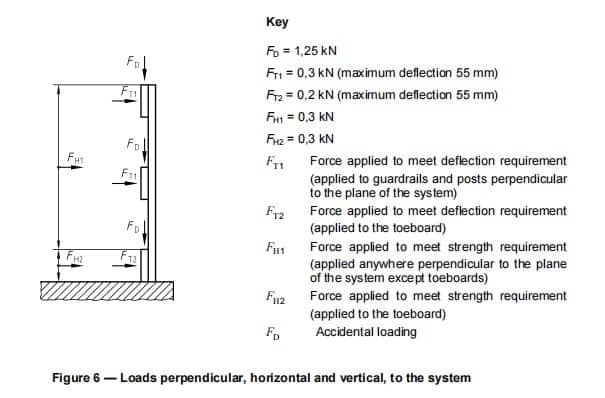
Each edge protection and each of its components, except toeboards, shall be designed to withstand a load
FH1 = 0,3 kN applied perpendicular to the axis of the post, see Figure 6.
6.3.1.2 Nets
The fixing of each net shall satisfy the load requirements for each class.
6.3.1.3 Toeboards
Each toeboards shall be designed to withstand a load FH2 = 0,2 kN at the most onerous position.
6.3.1.4 Area of application.
The loads referred to above are essentially point loads but they shall be assumed to be distributed upon a maximum area of 100 mm × 100 mm. For a net or a fencing structure, this load shall be assumed to be uniformly distributed upon a maximum area of 300 mm × 300 mm.
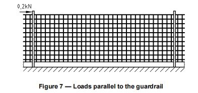
6.3.2 Loads parallel to the guardrail
Each edge protection and each of its components shall severally be capable of withstanding a horizontal
force of 0,2 kNat the most onerous point, see Figure 7.
6.3.3 Wind forces
6.3.3.1 General
The edge protection system shall withstand the force from wind load.
6.3.3.2 Evaluating wind forces
Wind forces, Fw, shall be calculated by assuming a wind velocity pressure to be applied on an effective area of the edge protection system, which is in general the projected area in the wind direction, not taking shielding into account. It shall be determined as follows:
Fw = Σ ( cf,i · qi · Ai )
where Fw is the resulting wind force
cf,i is the aerodynamic force coefficient for the edge protection components i (cf0 may be used uncorrected)
cf0 is the force coefficient of a component with infinite slenderness ratio
qi is the wind velocity pressure acting on the edge protection components i and shall be taken as 0,6 kN/m2
Ai is the reference area of the edge protection components
NOTE 1 The aerodynamic force coefficient cf, i appropriate to the cross section of the edge protection components in
question is given in ENV 1991-2-4.
For any cross-sections, not included in ENV 1991-2-4, the aerodynamic force coefficient may not be assumed to be less than 2,0, unless it has been established by testing.
NOTE 2 0,6 kN/m2 covers most wind conditions in Europe. More onerous conditions may occur. The wind velocity
pressure is based upon 40 meters height and an exposure period of 6 months and represents a wind speed of approximately 30 m/s.
Where wind is shown to be the governing load case, i.e. its effects are greater than the effect of the 0,3 kN specified, the edge protection shall be shown to withstand the wind load by calculation.
6.3.4 Load combinations
Load combinations, consisting of the following loads shall be designed for:
The horizontal loads according to cl. 6.3.1;
Wind load according to cl. 6.3.3, where qi may be taken to the value of 0,2 kN/m2.
Only the ultimate limit state has to be considered.
6.3.5 Serviceability limit state
The elastic deflection shall not be greater than 55 mm. The elastic deflection specified is defined as the deflection of the whole assembled system where either the force FT1 or FT2 is applied, at the most unfavorable position, see Figure 6.
6.3.6 Accidental loading
Any guardrail or intermediate guardrail or toeboard, regardless of its method of support, shall be capable of
resisting a downwards point load FD = 1,25 kN on a length of 100 mm. This also applies to any other component of the edge protection systems, such as a fencing structure, which has gaps in excess of 100 mm width,
see Figure 6.
This load shall be applied in the most unfavorable position of the edge protection system in a downward direction within a sector of ± 10° from the vertical.
6.4 Dynamic load
6.4.1 Edge protection system class A
This standard does not specify any dynamic loading.
6.4.2 Edge protection system class B
Class B edge protection shall be capable of absorbing the kinetic energy of 1100 J anywhere along with the protection up to a height of 200 mm above the working surface and 500 J at all higher parts.
The dynamic test specified in 7.5.2.1 shall be carried out. For class B edge protection to comply with the dynamic strength requirements of this standard, the sphericonical bag shall be arrested by the edge protection.
The system does not need to be serviceable after the test.
NOTE The intention is to consider a requirement for minimum deflection in a future revision of this standard. A relevant value of the minimum deflection is maybe 100 mm.
6.4.3 Edge protection system class C
Class C edge protection shall be capable of absorbing 2200 J of kinetic energy anywhere along with the protection
up to a height of 200 mm above the working surface.
The dynamic load test specified in 7.5.2.2 shall be carried out. For class C edge protection to comply with the requirements of this standard:
a) the cylindrical impactor shall not pass through the edge protection; and
b) the minimum deflection between the posts δmin (at a level 200 mm above the working surface) shall be
200 mm, at the moment when this energy has been absorbed.
The system does not need to be serviceable after the test.
NOTE The intention is that the deflection requirement of a minimum of 200 mm should be applied to every part of the
system (at a level 200 mm above the bottom), once a satisfactory practical solution is available, i. e. also to apply the requirements to the supports. At the time of writing this standard, the state-of-the-art means that it is not practicable to apply the deflection requirement to the posts or close by.
7. Test methods
7.1 General
The test shall be carried out in accordance with the requirements in clause 7 of this standard, and additionally,
relevant European Standards shall be used. Unless otherwise indicated in the following, testing shall be conducted by way of visual examination and measurement.
Each testing laboratory that carries out the test shall be able to demonstrate competence to carry out the relevant testing requirements of this standard.
NOTE Some countries have systems for national accreditation of testing laboratories.
7.2 Applying the loads
The loading point shall be a maximum of 100 mm × 100 mm or with smaller elements, the width of the element ×
100 mm.
When testing nets or fencing structures a distributing plate of a maximum of 300 mm × 300 mm (see 6.3.1.4) is required.
Stability of the test rig structure shall comply with 4.4 of EN 364:1992 (the natural frequency shall not be lower
than 100 Hz and the deformation shall not exceed 1 mm in the fixing point at a force of 20 kN).
7.3 Description of sample erection
The test sample shall comprise at least one bay in the most unfavorable length of the edge protection system or the worst possible configuration. Whichever the case the test sample shall be erected to represent the way
it is intended that it would be erected during use on-site, i.e. in accordance with the manufacturer’s instructions.
For friction (counterweighted) type protection, the base will be at 10o to the horizontal.
For edge protection fixed to a slab edge, see Figure 1, where the thinnest slab that can be gripped is 100 mm,
it shall be fixed to a rigidly fixed concrete slab of thickness 200 mm ± 5 mm.
For special applications, such as clamping to beam flanges, the edge protection system shall be tested in the way, it is intended to be clamped.
For counter-weighted systems, the test sample shall be erected on a surface that the coefficient of static friction between it and the base below the counterweight does not exceed 0,4. The value of the coefficient shall be established in accordance with annex A. The arithmetic average of four results shall be taken.
7.4 Tests for conformity with static load requirements (classes A and B)
7.4.1 General
A minimum of four separate representative samples shall be tested in each type of test.
The samples shall be set up in the most onerous configurations permitted in the manufacturer’s instructions.
When the most onerous case cannot be identified, either initial tests should be carried out to find it; or the second group of four samples should be tested.
Adjustment of results from tests shall be carried out in accordance with the method specified in EN 12811-3
where appropriate.
7.4.2 NOTE Sections10.2, 10.3, 10.6, and 10.10 of EN 12811-3 do not normally apply to temporary
edge protection. Tests for deflection
7.4.2.1 Preliminaries
Prior to each test, the system shall have a preliminary load of 0,1 kN applied to it. This load is to be held for one minute and then removed. The position of the system after this test shall be the datum for measurements in the full deflection test described in 7.4.2.2.
NOTE The purpose of this load is to ensure that the system is properly bedded and that any looseness is taken out.
7.4.2.2 Test procedure
For this test, the maximum test load is the same as the characteristic load specified in 6.3.1.1.
The load on the system shall be applied in five regular increments up to the maximum test load the maximum
the test load shall be held for one minute to determine the creep characteristics of the system.
7.4.2.3 During the loading of the load and the instantaneous deflection of the edge protection, δ shall be measured and recorded continually or at each load increment. Records
Record the maximum test load, the deflection δ at the maximum test load, and any increase in δ over the minute for which the maximum load is applied.
7.4.2.4 Evaluation of test records
The deflection at the maximum test load, δ, shall be adjusted, using statistical methods, which comply with
EN 12811-3.
7.4.3 Test for strength
7.4.3.1 Procedure for strength test
The loads shall be applied at the most adverse positions.
Establish the datum position of the edge protection, δ1.
The system shall be loaded in ten regular increments up to the maximum test load, Fmax (= γM x γF x QK),
where γM and γF are partial safety factors, see 6.2.1, and QK is the characteristic load for the case being considered, see 6.3.1.
This maximum test load shall be held for one minute. The instantaneous deflection of the edge protection, δ2
at this maximum load shall be measured.
During this period of maximum load, there should be no identifiable yielding, fracture, or separation of any part of the assembly.
The test load shall be removed and the residual deformation on the removal of the test load shall be measured.
This residual deflection shall not exceed 10 % of the deflection at maximum load.
The system should then be loaded in the same increments as up to the ultimate load, Ru, where there is an identifiable failure in either the system as a whole or in one of its component parts.
7.4.3.2 Records
Record the following:
a) datum position deflection δ1,
b) the instantaneous deflection at maximum load δ2.;
c) The residual deflection δ3;
d) The ultimate load RU;
e) Any observations relating to yielding, fracture, or separation of any part of the test assembly.
7.4.3.3 Evaluation of recorded results
Calculate the maximum deflection, δmax = δ2 – δ1
The ultimate load RU shall be adjusted, using statistical methods, which comply with EN 12811-3.
7.5 Tests for conformity with dynamic load requirements for classes B and C
7.5.1 Preliminaries
7.5.1.1 General
Prior to each test ensure that the system is properly bedded and that any slack in the system is taken out.
7.5.2 Test procedures for Class B and Class C
7.5.2.1 Strength test for lateral forces – Class B
7.5.2.1.1 Principle
A sphericonical bag shall be released in a controlled fall under gravity and swung towards the edge protection
the system at critical points, e.g. on the top and on the lowest practical part on the post; on the guardrails, and at a height of maximum 200 mm above the lowest part of the edge protection between two posts, to establish
whether the test sample can restrain the bag.
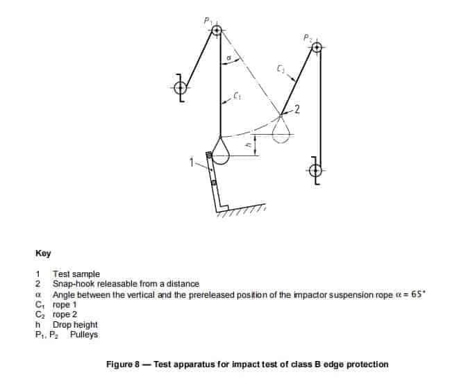
7.5.2.1.2 Test rig
The impact is obtained by the pendular fall of the sphericonical bag which is vertical at the impact point. The impacting body shall be held back to avoid a second impact.
A typical test apparatus is shown in Figure 8. The sphericonical bag is suspended by its ring to a rope, C1,
passing over a pulley, P1. P1 shall be attached to the frame in the position which ensures that:
when the bag is offered up to the test specimen its center touches the specimen at the required point;
at the point of impact, the rope shall be within ± 5° from the vertical;
the angle, α, between the rope, C1, and the point of impact is less than 65° when the bag is at its starting position.
7.5.2.1.3 The sphericonical bag
The sphericonical bag shall be in accordance with EN 596. The sphericonical bag shall be connected to the
rope by a device, C2, which can be released instantaneously from a distance.
7.5.2.1.4 Test drop height
To fulfill the requirements in clause 6.4.2 the drop height, h, see Figure 8, shall be 2,25 m when testing at a height of up to 200 mm above the lowest part of the edge protection (1100 J) and 1,0 m when testing other parts (500 J) of the edge protection.
7.5.2.1.5 Test procedure
Raise the sphericonical bag to its starting position. Release the sphericonical bag and allow it to impact with the edge protection system.
7.5.2.1.6 Test records Record whether the impactor is arrested by the edge protection assembly under test.
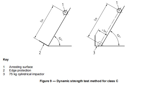
7.5.2.2 Strength test for class C
7.5.2.2.1 Principle
The test impactor (cylindrical) according to EN 1263-1 shall roll down a ramp towards the lowest parts (see 6.4.3) of the edge protection system at critical points:
on the post, and
between the posts;
see Figure 9.
At the base of the test ramp it shall be possible to fix the sample of the edge protection according to the manufacturer’s instruction as it would be on site.
Provisions shall be made to measure the instantaneous deflection at the center of the area of contact.
7.5.2.2.2 Test procedure
The test shall be carried out in accordance with EN 1263-1.
Position the cylindrical impactor so that the center of gravity travels 5,0 m, as shown in Figure 9. Establish the
the datum for measurement of the deflection of the edge protection δ 1.
Position the cylinder on the ramp so that it rolls towards the edge protection system to impact with it at critical
points, see 7.5.2.2.1.
Allow the cylinder to roll down the slope and impact with the edge protection at the required positions. On the points of impact, measure and record the instantaneous deflections of the edge protection, δ2.
The impactor shall be left in contact with the edge protection for a period not less than three minutes.
7.5.2.2.3 Test records
Record the following:
a) datum position of the edge protection assembly under test, δ1;
b) The maximum instantaneous deflection, δ2;
c) Whether the impactor is held for three minutes.
7.5.2.2.4 Evaluation of recorded results
Calculate the minimum-maximum deflection δmin = δ2 – δ1
Adjust the value of δmin using statistical methods, which comply with EN 12811-3.
7.6 Test reports
The test reports shall follow the outlines given in clause 9 of EN 12811-3:2002 but shall include at least the
following:
description of the configuration of the edge protection system;
number, title, and date of issues of this European Standard;
description of the sample including material specification;
photographs of and description of the test rig structure;
description of the foundation during the test;
detailed description of the entire test procedure;
test result;
confirmation that the test was carried out in accordance with this standard.
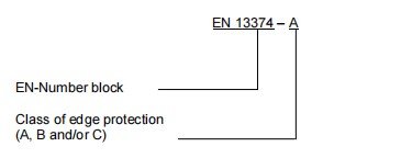
8. Designation
Example of designation for an edge protection system class A
9. Marking
The following purpose-made components shall be marked: principal guardrails; intermediate guardrails; intermediate protection (e.g. fencing); toe-boards; posts; counterweights. The marking shall be clearly visible and shall be so arranged that it will remain legible for the service life of the product, and contain the following: EN 13374; type of edge protection system: A, B, or C; name/identification of the manufacturer or supplier; year and month, in that order, of manufacture or serial number; counterweights shall be marked with their weights in kilograms.
For components specified by the manufacturer but not supplied by him, in addition to any marking specified
for the component, there shall be marked to identify the edge protection system to which they relate.
10. Information to be given to the site
10.1 General requirements
A set of instructions forming a manual shall be provided. They will be part of the basis of the assessment and,
after successful completion, their content shall be supplied with the components as part of the edge protection
system.
10.2 Principal contents
The main instructions in the manual shall include:
a list giving each component and a description from which it can be identified for example with a drawing;
instructions for the sequence of assembling, including fixing to the structure unless it depends on friction;
instructions for dismantling the components and how to handle them;
layouts of configurations allied with their classes and their dimensions;
a statement of limitations of use with reference to wind velocity pressure, to ice and to snow;
an explanation of the classification and the range of applications and any limitations of the system described;
a full specification of the items which are not purpose-made components;
counterweighted edge protection systems shall state the minimum clearance from the edge;
loads imposed on the structure from which it is supported;
criteria for rejecting components that are worn or damaged;
any instructions for storage, maintenance, or repair which the manufacturer considers appropriate;
information about applications for which the edge protection system is suitable, according to relevant national rules.
The instructions shall also state the following:
after a fall of a person or an object towards or into the edge protection system, and its accessories, the
system shall only be re-used after having been inspected by a competent person.
11. Assessment
An assessment shall be carried out by a person or an organisation different from the original designing person
and organisation.
On completion of a successful evaluation, a statement to that effect shall be given. This statement shall identify the reference number of all examinations and the assessor’s report shall include:
identification of the particular set of components examined;
identification of the standards used
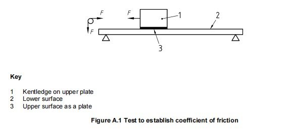
Annex A
(normative)
Test to establish the coefficient of friction
A.1 Principle of the Test
A horizontal force is applied to a specified weight resting on a level platform – see Figure A.1. The applied
force is steadily increased until the specified weight starts to move. The horizontal force required to initiate
movement is used in calculating the coefficient of static friction between the weight and the level platform.
A.2 Apparatus
A plate A: 300 mm long × 100 mm wide and with the necessary thickness to be representative of the material
to be tested.
A block of mass 50 kg which can be supported on the plate A.
A platform surfaced with the material B with the necessary thickness to be representative of the material to be
tested.
A.3 Procedure
Support the platform surfaced with B horizontally and level to within ± 0,5 degrees. Prevent movement of the
platform in the direction of the applied force. Place the plate A on the platform and load it with the 50 kg block.
Apply the horizontal force F to the 50 kg block in increments of 50 N (see Figure A.1) as close as possible to
the underside of the plate A.
A.4 Test records
Record the force at which the specified weight moves at least 10 mm along the platform.
A.5 Evaluation of test records
The coefficient of static friction, µ, shall be calculated for each test using equation [A.1] given below:
Coefficient of static friction,
µ = F / (M + m) × g (A.1)
where
F = force in Newton
M = mass 50 kg
m = mass of the plate
g = 9,81 ms–2
Calculate the arithmetic average of µ from a minimum of four tests. This average value shall be taken as the
characteristic coefficient of static friction, µ, between the plate A and the surface B.
Annex B
(informative)
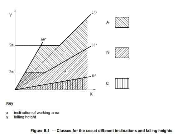
Appropriate classes for the use at different inclinations and falling
heights
The edge protection specified in this standard is for three different classes. This annex gives advice on which
class to use depending on the angle of the working surface from the horizontal and the possible falling height.
Class A should not be used if the angle of the working surface is more than 10o.
Class B may be used if the angle is less than:
30° without limitation of the falling height, or;
60° and the falling height is less than 2 m.
Class C may be used if the angle is between:
30° and 45° without limitation of the falling height, or;
45° and 60° and the falling height is less than 5 m.
If the angle is more than 60° or more than 45° and the falling height is more than 5 m, edge protection systems are not appropriate as protection. At greater falling heights the system can be placed higher on the sloping area, for example, every 2 m and 5 m of falling height for system class B and C respectively.